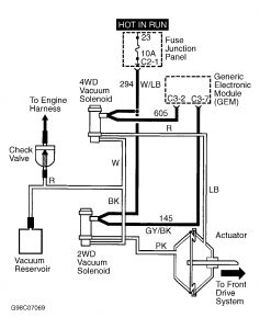
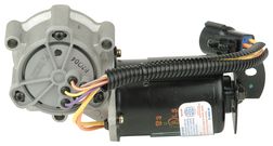
DESCRIPTION & OPERATION The electronically controlled 44-05 transfer case has A4WD (automatic), 4WD HIGH and 4WD LOW ranges. Transfer case operation is conducted by 2 motor driven shift forks (2WD to 4WD and 4WD HIGH to 4WD LOW) and internal electromagnetic multi-disc clutch assembly (automatic operation). When in A4WD, system uses 2 hall effect type front and rear drive shaft speed sensors to compare front and rear drive shaft speeds. When drive shaft speeds differ by a predetermined amount the Generic Electronic Module (GEM) activates internal clutch to lock transfer case and equalize drive shaft speeds. At rest and cruising conditions, the GEM activates the transfer case clutch at a minimum duty cycle. The clutch duty cycle is longer when slipping of front or rear axle is detected, during heavy acceleration or with very light throttle at speeds greater than 40 MPH. MODULE LOCATION Generic Electronic Module (GEM) is mounted on fuse block, below left side of dash panel. INPUT DEVICES Brake On/Off (BOO) Switch The PCM receives a signal from the BOO switch when the brake switch is operated. The GEM and PCM are linked by a communication network. When shifting into or out of LOW range, the GEM requires brake pedal to be depressed. Clutch Pedal Position (CPP) Switch The PCM receives a signal from the CPP switch when the clutch pedal is depressed. The GEM and PCM are linked by a communication network. When shifting into or out of LOW range, the GEM requires clutch pedal to be depressed. Drive Shaft Speed Sensors Hall effect type sensors monitor front and rear drive shaft speeds and input information to GEM. This input is used primarily to control A4WD (automatic) operation. 4WD Mode Switch Instrument panel mounted switch sends input signal to GEM pertaining to commanded transfer case range. Shift Motor Sense Plate The shift motor sense plate is an integral part of the electric shift motor. The sense plate sends shift motor position input to GEM. Throttle Position (TP) Sensor The TP sensor is a potentiometer mounted to the engine throttle body. The PCM receives a signal from TP sensor relaying throttle plate position. The GEM and PCM are linked by a communication network. Signal is used by the GEM to control A4WD clutch. Transmission Range Switch The TR sensor is a digital type. The PCM monitors a series of step down resistors in TR sensor that act as a voltage divider. The voltage signal corresponds with position of transaxle range selector lever. The GEM and PCM are linked by a communication network. The TR sensor also contains neutral/start and backup light circuits. Malfunction of TR sensor may cause transfer case not to shift. Improper transmission shifting or shift selection and no engine cranking may also result. Vehicle Speed Sensor (VSS) The VSS is a magnetic pickup that sends output speed signal to the PCM. The GEM and PCM are linked by a communication network. When shifting into or out of LOW range, the GEM requires vehicle speed to be less than 3 MPH. OUTPUT DEVICES Transfer Case Clutch Relay Pulse width modulated signal operated relay that operates internal electromagnetic clutch. 4WD Shift Motor Relay Actuates electric shift motor mounted to transfer case. Shift motor drives a rotary cam which moves mode fork and range fork inside transfer case. 4WD/2WD Vacuum Solenoids Both solenoids are attached to upper RH side of engine compartment dash panel. Solenoids alternately route vacuum to vacuum motor which engages/disengages center axle disconnect collar in front axle assembly. See Fig. 1. Fig. 1: 4WD Front Axle Vacuum Diagram
11/14/2009 .
TEST A: A4WD INDICATOR FLASHES WHEN A4WD MODE IS SELECTED 1. Check Ignition States; Monitor GEM PID IGN_GEM - Turn ignition off. Connect NGS tester. Monitor Generic Electronic Module (GEM) Parameter Identification (PID) Ignition Switch Status (IGN_GEM) while turning ignition switch through START, RUN, OFF and ACC positions. If values agree, go to next step. If values do not agree, see appropriate STEERING COLUMN SWITCHES article in the ACCESSORIES/SAFETY EQUIPMENT section. 2. Retrieve DTCs - Retrieve and document continuous DTCs. Clear continuous DTCs. Retrieve on-demand DTCs. If DTCs are recorded, go to appropriate step(s). See DTC/TEST OR STEP table. If no DTCs are retrieved, go to next step. NOTE: Vehicle must be driven in A4WD at 30 MPH or greater and/or encounter a slip condition before A4WD indicator light will flash for certain faults. NOTE: In next step, if DTC B1342 is retrieved, replace GEM. Clear DTCs and retest system.
Tuesday, February 12th, 2019 AT 6:39 PM
(Merged)


