TRACK & MOTOR ASSEMBLY
Removal
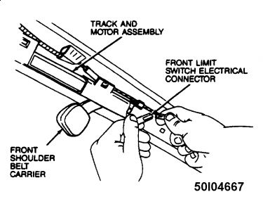
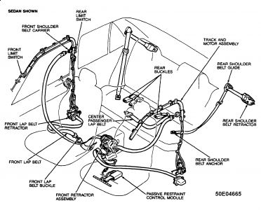
Disconnect battery ground cable. Unbuckle shoulder belt from carrier. See Fig. 5 . Cycle the shoulder belt carrier to the B-pillar (retracted position).
Remove A-pillar (Front Limit Switch) and B-pillar (Rear Limit Switch) trim panels. Disconnect front limit switch electrical connector. See Fig. 5 .
Fig. 5: Shoulder Belt Carrier & Front Limit Switch Connector

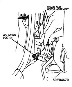
Disconnect 2 electrical connectors from track and motor assembly. Remove all track and motor assembly attaching bolts and screws. See Fig. 8 . Remove track and motor assembly.
Fig. 8: Removing Mounting Bolts (3 Bolts)

Installation
Place track and motor assembly and hold into position with one of the mounting bolts. See Fig. 9 . Connect the 2 electrical connectors. Install the motor mounting bolts and tighten to 69-104 INCH Lbs. (8-12 N.m). Install the 2 track mounting bolts at the rear limit switch and tighten to 13-19 Ft. Lbs (18-25 N.m).
Install the remaining track mounting bolts and tighten to 69-104 INCH Lbs. (8-12 N.m). Connect the front limit switch electrical connector. Install A-pillar and B-pillar trim panels. Connect shoulder belt to the carrier.
Connect battery ground cable. Cycle passive restraint system to verify proper operation.

Friday, March 26th, 2010 AT 5:06 PM


