TEST E: WIPERS INOPERATIVE AT LOW SPEED
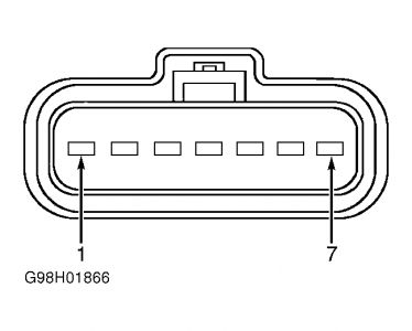
Turn ignition switch to LOCK position. Disconnect wiper motor harness connector C151. Turn ignition switch to RUN position. Set wiper switch for low speed operation. Measure voltage between terminals No. 6 (Dark Blue/Orange wire) and No. 5 (Yellow/Red wire) at wiper motor harness connector C151. See Fig. 4. If battery voltage does not exist, go to next step. If battery voltage exists, test wiper motor. See WIPER MOTOR under COMPONENT TESTS. If wiper motor is okay, repair wiper linkage as necessary.
Turn ignition switch to LOCK position. Disconnect Wiper Control Module (WCM) harness connector C294. Measure resistance between ground and terminal No. 8 (Dark Blue/Orange wire) at WCM harness connector C294. See Fig. 2. If resistance is greater than 10 k/ohms, go to next step. If resistance is 10 k/ohms or less, repair short to ground in Dark Blue/Orange wire between wiper control module and wiper motor.
Measure resistance in Dark Blue/Orange wire between terminal No. 6 at wiper motor harness connector C151 and terminal No. 8 at WCM harness connector C294. If resistance is 5 ohms or less, go to next step. If resistance is greater than 5 ohms, repair open in Dark Blue/Orange wire between wiper control module and wiper motor.
Set wiper switch to low speed position. Measure resistance between terminals No. 1 (Orange wire) and No. 7 (Brown/White wire) at WCM harness connector C294. If resistance is 3500-4500 ohms, replace wiper control module. If resistance is not 3500-4500 ohms, replace multifunction switch.
fig 4

fig 2

Wiring diagram is attached below
Image (Click to make bigger)
Wednesday, December 17th, 2008 AT 2:19 PM


