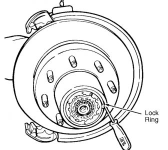
Dana 44 IFS, Dana 44 IFS-HD and Dana 50 IFS.
See Figures 1 and 2.
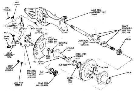
Fig. 1: Spindle, left shaft and joint installation for the Dana 44 and 50 front axles
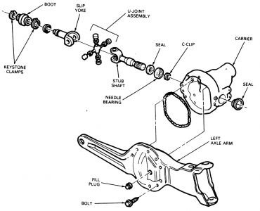
Fig. 2: Carrier and slip yoke, stub shaft installation on the Dana 44 and 50 IFS1.Raise and support the front end on jackstands.
2.Remove the front wheels.
3.Remove the calipers.
4.Remove the hub/rotor assemblies.
5.Remove the nuts retaining the spindle to the steering knuckle. Tap the spindle with a plastic mallet to remove it from the knuckle.
6.Remove the splash shield.
7.On the left side, pull the shaft from the carrier, through the knuckle.
8.On the right side, remove and discard the keystone clamp from the shaft and joint assembly and the stub shaft. Slide the rubber boot onto the shaft and pull the shaft and joint assembly from the splines of the stub shaft.
9.Place the spindle in a soft-jawed vise clamped on the second step of the spindle.
10.Using a slidehammer and bearing puller, remove the needle bearing from the spindle.
11.Inspect all parts. If the spindle is excessively corroded or pitted it must be replaced. If the U-joints are excessively loose or don't move freely, they must be replaced. If any shaft is bent, it must be replaced.
12.Clean all dirt and grease from the spindle bearing bore. The bore must be free of nicks and burrs.
To install:
13.Insert a new spindle bearing in its bore with the printing facing outward. Drive it into place with drive T80T-4000-S for F-150 and Bronco and F-250, or T80T-4000-R for the F-350, or their equivalents. Install a new bearing seal with the lip facing away from the bearing.
14.Pack the bearing and hub seal with grease. Install the hub seal with a driver.
15.Place the thrust washer on the axle shaft.
16.Place a new slender on the axle shaft.
17.Install the rubber V-seal on the slinger. The seal lip should face the spindle.
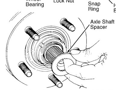
18.Install the plastic spacer on the axle shaft. The chamfered side of the spacer should be inboard against the axle shaft.
19.Pack the thrust face of the seal in the spindle bore and the V-seal on the axle shaft with heavy duty, high temperature, waterproof wheel bearing grease.
20.On the right side, install the rubber boot and new keystone clamps on the stub shaft and slip yoke. The splines permit only one way of meshing so you'll have to properly align the missing spline in the slip yoke with the gapless male spline on the shaft. Slide the right shaft and joint assembly into the slip yoke, making sure that the splines are fully engaged. Slide the boot over the assembly and crimp the keystone clamp.
21.On the left side, slide the shaft and joint assembly through the knuckle and engage the splines in the carrier.
22.Install the splash shield and spindle on the knuckle. Tighten the spindle nuts to 60 ft. lbs.
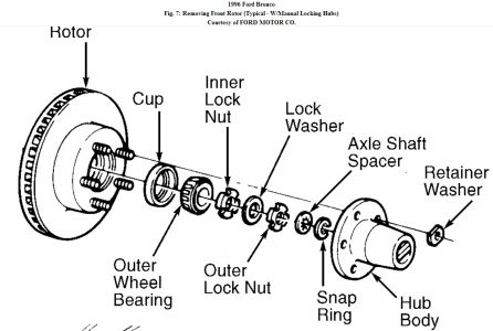
23.Install the rotor on the spindle. Install the outer wheel bearing into the cup. Make sure that the grease seal lip totally encircles the spindle.
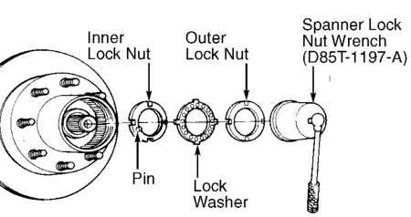
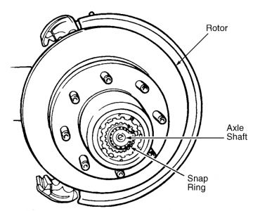
24.Install the wheel bearing, locknut, thrust bearing, snapring and locking hubs.
25.Install the caliper.
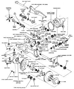
1.Raise and support the front end on jackstands placed under the radius arms.
2.Remove the wheels.
3.Remove the calipers and wire them out of the way. Don't disconnect the brake lines.
4.Support the axle arm with a jack and remove the upper coil spring retainers.
5.Lower the jack and remove the coil springs, spring cushions and lower spring seats.
6.Disconnect the shock absorbers at the radius arms and upper mounting brackets.
7.Remove the studs and spring seats at the radius arms and axle arms.
8.Remove the bolts securing the upper attachment to the axle arm and the lower attachment to the axle arm.
9.Disconnect the vent tube at the housing. Remove the vent fitting and install a 1/8 inch; pipe plug.
10.Remove the pivot bolt securing the right side axle arm to the crossmember. Remove and discard the boot clamps and remove the boot from the shaft. Remove the right drive axle assembly and pull the axle shaft from the slip shaft.
11.Support the housing with a floor jack. Remove the bolt securing the left side axle assembly to the crossmember. Remove the left side drive axle assembly.
12.Installation is, basically, a reversal of the removal procedure. Always use new boot clamps. Observe the torque values listed in of this information.
� � � Driveshaft-to-flange: 15-20 ft.lb.
� � � Spindle connecting rod-to-knuckle: 70-100 ft.lb.
Sunday, October 26th, 2008 AT 6:41 PM


