Hi guys. Allow me to add some clarification. All relays use an electromagnetic coil of wire to pull on a movable contact to turn on the high-current switching contacts. When first energized, current builds up slowly, not instantly, as that current creates a magnetic field that opposes the current creating it. That is normal, takes just a few microseconds, and is exactly the same thing that happens in an ignition coil.
When that current is switched off, (think of opening breaker points on an older car), current flow has no choice but to go to 0.00 amps instantly. That extremely rapid collapse of the electromagnetic field creates an "inductive kick" that develops a huge voltage spike. In an ignition coil that spike is at the heart of how the circuit works. It can be as high as 300 volts. That gets transformed, or multiplied up to 15,000 to 40,000 volts in the secondary to fire the spark plugs. That inductive kick is desirable and necessary.
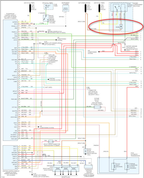
That same inductive kick occurs in the relay's coil when it is switched off, but here that used to be turned on and off by a mechanical switch. Those don't give a hoot about voltage spikes. Today relays are usually turned on and off by computer circuitry. Those transistors have very specific current and voltage limitations that are designed in for specific applications. Transistors are extremely intolerant of those voltage spikes. Once a transistor shorts, it's done and that computer has to be replaced. To prevent that damage, they put a diode across the coil of wire. It's in there backward, so when it's energized, it's like that diode isn't even there. (Diodes are one-way valves for electrical current flow). It's when that voltage spike is developed, with its reversed polarity, that the diode becomes "forward biased", meaning the voltage polarity of that spike turns the diode on, then it conducts a little current to short out that spike. That removes the threat of damage to the computer controls.
Generic relays often do not have a diode. If one is needed, it is installed in the rest of the circuit. It could even be soldered to the terminals on the relay's socket.
As a point of interest, if you see the 1" cube gray relays in a lot of GM vehicles, with four terminals instead of five, and they're in a square pattern, those relays do not have diodes. Instead, they use a resistor that under normal operation is high enough in value as to have no effect on circuit operation. When those relays are turned off, the voltage spikes kind of get absorbed by the resistor. They aren't nearly as effective, but they do a good enough job, and the advantage is those relays can be installed into the socket two ways and they'll work just fine either way.
When the relay has a built in diode, the coil has to be wired with the correct polarity. If you try to use one in a custom project and connect the coil backward, you'll have a short circuit and usually some smoke. You can't plug them in wrong in the relay box. The polarity was designed in by the engineers.
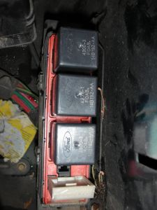
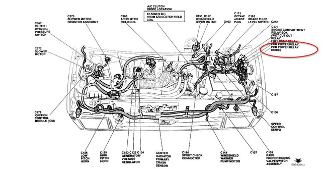
To finally answer the question, Ford often prints "Diode" on the relay covers to denote there's a diode in there across the coil. We don't customarily see that on other relays, hence the confusion. It's just a regular relay, but they're telling you there is voltage spike suppression built in.
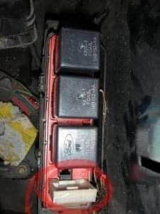
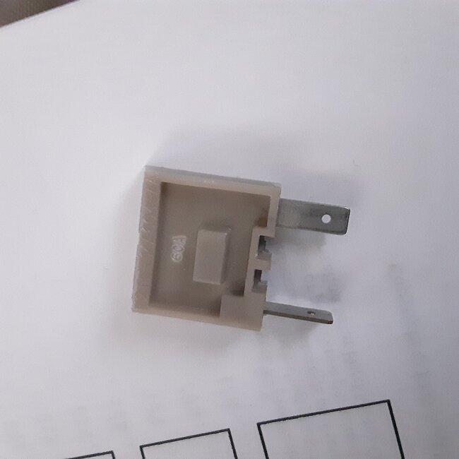
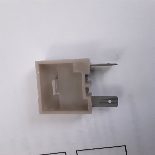
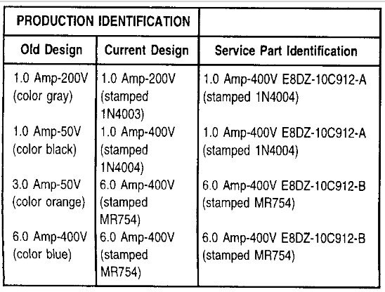
In other applications, Ford was famous for trying to use up a huge inventory of parts purchased when building older models. Instead of letting those sit on shelves for years, they find a place where they can be used on a current model, but they might have to add something, in this case a separate diode. Rather than buy millions of new relays and let millions of in-stock relays sit, they just design a diode that can be plugged into the circuit. Because those diodes do have that polarity, the terminals are oriented in such a way as the assembly can't be plugged in wrong. Those could be used with a relay, or, as Wrenchtech mentioned, to isolate one circuit from back-feeding another circuit, such as when they both share a common ground. In those circuits, they can be expected to have to pass a certain amount of current. The more current and the higher voltage a diode can handle, the more expensive it is. They will have different diodes with different ratings so they can use one that is the least expensive they can get away with, and spend more only for those that are used in higher-current applications. This is where you might be able to switch them around, but typically if those differences are important enough, they'll use different terminal spacing so they can be mixed up.
Thursday, January 12th, 2023 AT 8:34 PM
