Welcome back:
Chances are that is the problem. Here are the directions for replacement. The attached pics correlate with the directions.
___________________________________________
FRONT
pic 1
REMOVAL
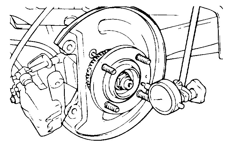
1. Remove the wheel and tire.
Pic 2
2. Remove the drive shaft nut.
3. Remove the vehicle speed sensor from the axle assembly.
Pic 3
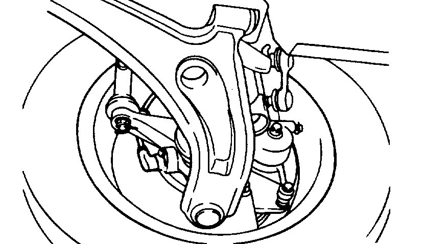
4. Remove the front brake assembly from the knuckle and suspend with a wire.
NOTE: Brake hose does not need to be disconnected from brake caliper. Be careful not to depress brake pedal, or piston will pop out.
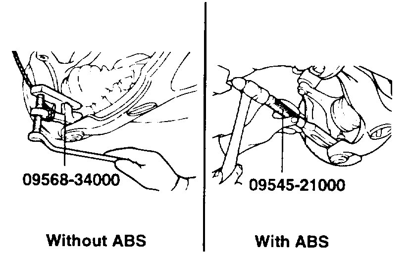
5. Disconnect the lower arm ball joint from the knuckle using the special tool.
Pic 4
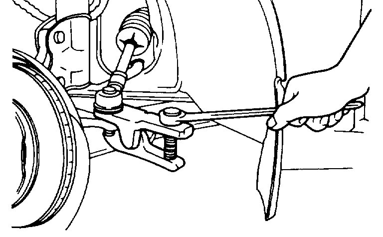
6. Disconnect the tie rod and ball joint from the knuckle using the special tool.
NOTE:
1) Be sure to tie a cord to the special tool and to a nearby part.
2) Loosen the nut but do not remove it.
Pic 5
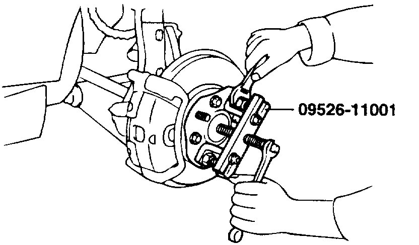
7. Disconnect the drive shaft from the hub using the special tool.
Pic 6
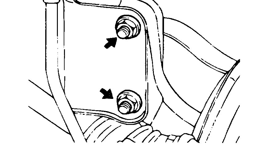
8. Remove the hub and knuckle as an assembly from the strut.
INSPECTION
1. Check the hub for cracks and the splines for wear.
2. Check the snap ring for cracking or damage.
3. Check the steering knuckle for cracks.
DISASSEMBLY
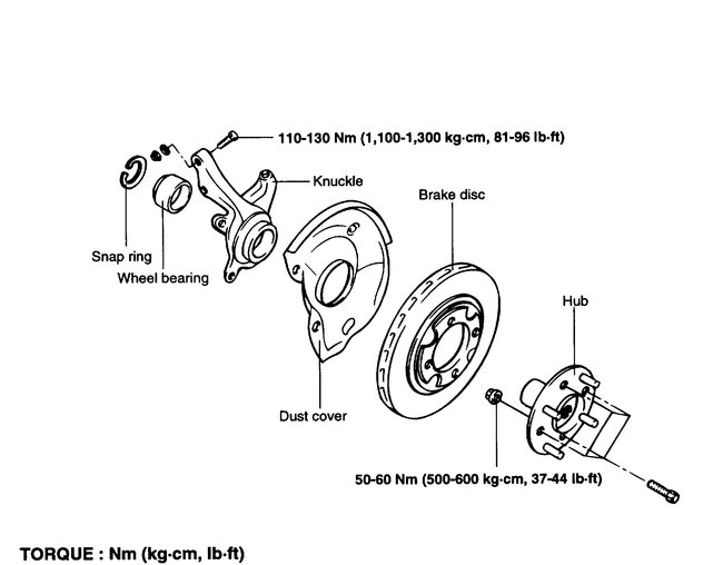
pic 7
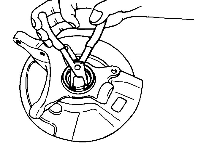
1. Remove the snap ring.
Pic 8
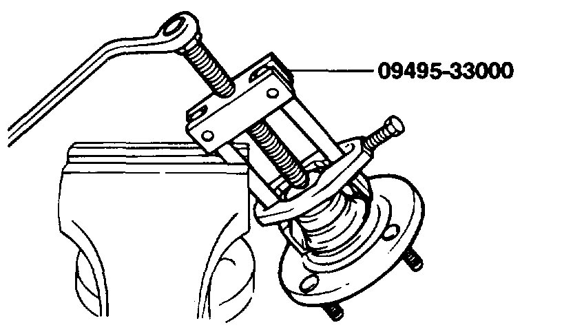
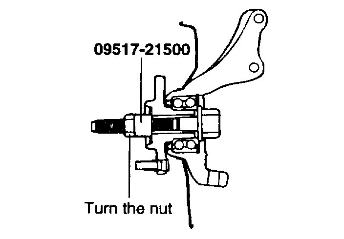
2. Attach the special tools to the knuckle and hub.
3. Secure the knuckle in a vise.
4. Tighten the nut of the special tool and remove the hub from the knuckle.
NOTE: When removing wheel hub or wheel bearing from knuckle, replace wheel bearing assembly (outer race, inner races and grease seals) with a new one.
Pic 9
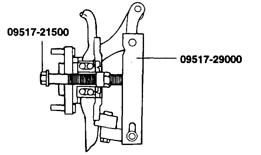
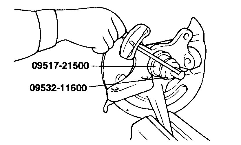
5. Using the special tool, remove the wheel bearing inner race (outside) from the front hub.
Pic 10
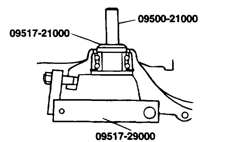
6. Install the inner race (outside) that was removed from the hub to the wheel bearing, and then use the special tool to remove the wheel bearing.
INSPECTION
1. Check the hub and brake disc mounting surfaces for scoring and contamination.
2. Check the knuckle inner surface for scoring and cracks.
3. Check for a defective bearing.
REASSEMBLY
1. Fill the wheel bearing with multipurpose grease.
2. Apply a thin coating of multipurpose grease to the knuckle and bearing contact surfaces.
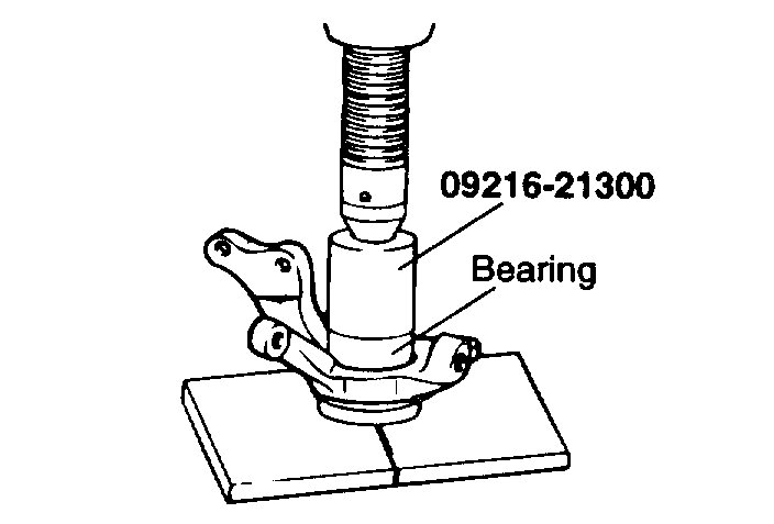
Pic 11
3. Press-in the bearing by using the special tool.
NOTE: Do not press inner race of wheel bearing assembly.
Pic 12
4. Install snap ring into groove of knuckle.
Pic 13
pic 14
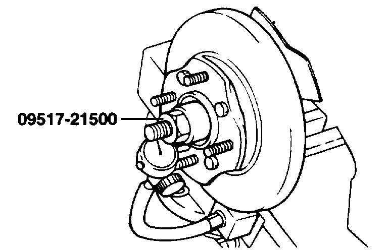
5. Measure the hub bearing starting torque.
Pic 15
6. If the starting torque is 0 Nm (0 inch lbs.), Measure the hub bearing axial play.
Pic 16
7. If the hub axial play exceeds the limit while the nut is tightened to 200 - 260 Nm (2,000 - 2,600 kg-cm, 148 - 192 ft. Lbs.), The bearing, hub and knuckle have not been install correctly.
Repeat the disassembly and assembly procedure.
8. Remove the special tool.
INSTALLATION
1. Install parts to the torque specifications.
2. Be sure to install the washer and wheel bearing nut in the specified direction.
3. After installing the wheel, lower the vehicle to the ground and tighten the wheel bearing nut.
4. If the position of the split pin holes do not match, tighten the nut up to 260 Nm (2600 kg-cm, 188 ft. Lbs.) Maximum.
5. Install the split pin in the first matching holes and bend it over.
________________________________________
Let me know if this helps or if you have other questions.
Take care,
Joe
Images (Click to make bigger)
SPONSORED LINKS
Sunday, May 19th, 2019 AT 6:33 PM
