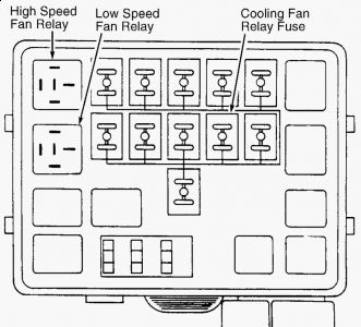
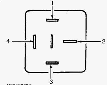
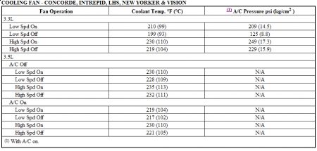
CONCORDE, INTREPID, LHS, NEW YORKER & VISION The dual cooling fans operate simultaneously and are turned on whenever coolant temperature sensor or A/C pressure transducer (on compressor discharge line) sends a signal to the Powertrain Control Module (PCM). The PCM turns on the fans through the low and high speed fan motor relays. When A/C is not operating, cooling fan operation is controlled by coolant temperature sensor signal to PCM. Signal indicates when coolant has reached a specified temperature. See COOLING FAN OPERATING TEMPERATURE (CONCORDE, INTREPID, LHS, NEW YORKER & VISION) table. Fans will operate independently of coolant temperature when A/C pressure signal reaches a predetermined level. Fans will not operate during engine cranking, regardless of coolant temperature. High and low fan speed relays are in the relay box under the hood. Concorde, Intrepid, LHS, New Yorker & Vision 1. Check for loose connections at fan motor and fan motor relay. If all connections are okay, check for Diagnostic Trouble Codes (DTCs). If DTCs are not present, go to next step. Ã Â Â TESTS W/CODES - 2.5L (for Sebring Coupe & Avenger) Ã Â Â TESTS W/CODES - 2.5L (for Cirrus & Stratus) Ã Â Â TESTS W/CODES (for 3.5L LHS) Ã Â Â TESTS W/CODES - 3.3L (for Concorde, Intrepid & Vision) Ã Â Â TESTS W/CODES - 3.5L (for Concorde, Intrepid & Vision) 2. With ignition on and engine at normal operating temperature, check for battery voltage on both sides of cooling fan relay fuse. Cooling fan fuse and high and low cooling fan relays are located in fuse/relay block, in front of left strut tower. See Fig. 8 . 3. If battery voltage is not present, repair shorted or open Red/Light Green wire circuit. If battery voltage is present, remove low speed or high speed fan motor relay. Using ohmmeter, ensure continuity exists between terminals No. 1 and 3. See Fig. 9 . If continuity does not exist, replace relay. 4. Connect battery positive to terminal No. 1 and battery negative to terminal No. 3. See Fig. 9 . Check continuity between relay terminals No. 2 and 4. Continuity should not exist with battery voltage disconnected. Replace relay is continuity is not specified. NOTE: DTCs are obtained by using DRB scan tool. For additional information, see appropriate TESTS W/CODES article in the ENGINE PERFORMANCE section.
SPONSORED LINKS
Saturday, November 28th, 2009 AT 11:27 AM


