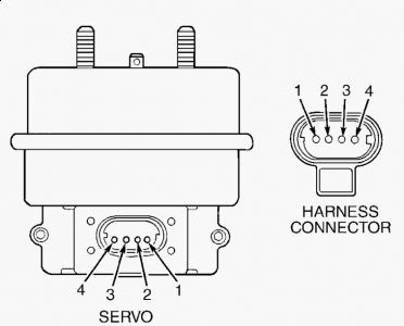
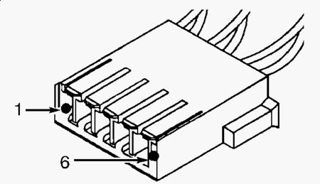
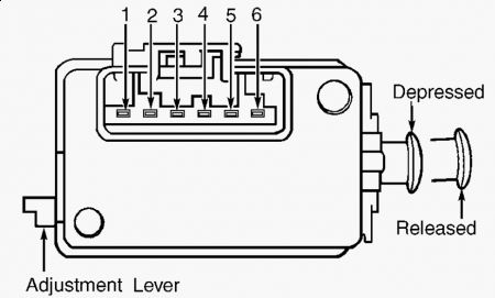
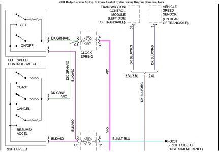
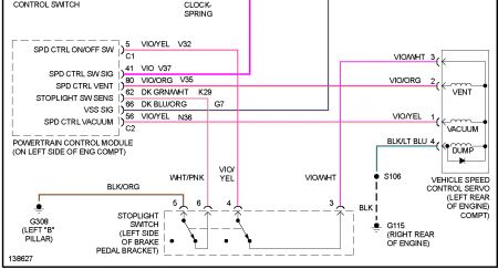
DTC P1595: SPEED CONTROL SOLENOID CIRCUITS DTC P1683: SPEED CONTROL POWER RELAY OR 12V DRIVER CIRCUIT NOTE: Both DTCs are diagnosed using the same test. After repairs, perform TEST VER-4A under VERIFICATION TESTS. DTC P1595 will set if vacuum and vent solenoids do not respond when actuated by PCM. DTC P1683 will set if Speed Control (S/C) power supply circuit is open or shorted to ground. Possible Causes Ground circuit open. "Â Brake switch output circuit open. "Â S/C power supply circuit open or shorted. "Â S/C servo defective. "Â S/C vacuum solenoid control circuit open or shorted. "Â S/C vent solenoid control circuit open or shorted. "Â Brake switch defective or out of adjustment. "Â Defective PCM. "Â Testing Turn ignition on. Turn Speed Control (S/C) on. Using scan tool, actuate S/C vent solenoid. Using scan tool, actuate S/C vacuum solenoid. If vacuum solenoid in S/C servo does not click, go to next step. If vent solenoid in S/C servo does not click, go to step 6 . If both solenoids do not click, go to step 10 . If both solenoids click, go to step 15 . 1. Turn ignition off. Disconnect S/C servo connector. Inspect connector and clean or repair as necessary. Turn ignition on. Turn S/C switch on. With test light connected to battery voltage, probe S/C servo connector terminal No. 1 (Violet/Yellow wire). See Fig. 4 . Using scan tool, actuate S/C vacuum solenoid. If test light does not blink off and on, go to next step. If test light blinks on and off, replace S/C servo. See SPEED CONTROL SERVO under REMOVAL & INSTALLATION. 2. Disconnect PCM connectors. Inspect connectors and clean or repair as necessary. Using DVOM, measure resistance of Violet/Yellow wire between S/C servo connector terminal No. 1 and PCM connector C2 terminal No. 56. See Fig. 3 . If resistance is less than 5 ohms, go to next step. If resistance is 5 ohms or more, repair open on Violet/Yellow wire. 3. Using DVOM, measure resistance between ground and S/C servo connector terminal No. 1 (Violet/Yellow wire). If resistance is 5 ohms or more, go to next step. If resistance is less than 5 ohms, repair short to ground on Violet/Yellow wire. 4. Replace PCM. 5. Turn ignition off. Disconnect S/C servo connector. Inspect connector and clean or repair as necessary. Turn ignition on. Turn S/C switch on. With test light connected to battery voltage, probe S/C servo connector terminal No. 2 (Violet/Orange wire). See Fig. 4 . Using scan tool, actuate S/C vent solenoid. If test light does not blink off and on, go to next step. If test light 6.blinks on and off, replace S/C servo. See SPEED CONTROL SERVO under REMOVAL & INSTALLATION. Disconnect PCM connectors. Inspect connectors and clean or repair as necessary. Using DVOM, measure resistance of Violet/Orange wire between S/C servo connector terminal No. 2 and PCM connector C2 terminal No. 80. If resistance is less than 5 ohms, go to next step. If resistance is 5 ohms or more, repair open on Violet/Orange wire. 7. Using DVOM, measure resistance between ground and S/C servo connector terminal No. 2 (Violet/Orange wire). If resistance is 5 ohms or more, go to next step. If resistance is less than 5 ohms, repair short to ground on Violet/Orange wire. 8. Replace PCM. 9. Turn ignition off. Disconnect S/C servo connector. Inspect connector and clean or repair as necessary. Turn ignition on. Turn S/C switch on. Connect test light between S/C servo connector terminal No. 3 (Violet/White wire) and ground. See Fig. 4 . If test light does not illuminate, go to next step. If test light illuminates, replace S/C servo. See SPEED CONTROL SERVO under REMOVAL & INSTALLATION. 10. Turn ignition off. Disconnect brake switch connector. Using DVOM, measure resistance of Violet/White wire between brake switch harness connector terminal No. 3 and S/C servo connector terminal No. 3. See Fig. 2 and Fig. 4 . If resistance is less than 5 ohms, go to next step. If resistance is 5 ohms or more, repair open on Violet/White wire. 11. Turn ignition on. Turn S/C switch on. With test light connected to ground, probe brake switch harness connector terminal No. 4 (Violet/Yellow wire). If test light does not illuminate, go to next step. If test light illuminates, replace brake switch. See BRAKE SWITCH under REMOVAL & INSTALLATION. 12. Turn ignition off. Disconnect PCM connectors. Inspect connectors and clean or repair as necessary. Using DVOM, measure resistance of Violet/Yellow wire between brake switch harness connector terminal No. 4 and PCM connector C1 terminal No. 5. See Fig. 2 and Fig. 3 . If resistance is less than 5 ohms, go to next step. If resistance is 5 ohms or more, repair open on Violet/Yellow wire. 13. Replace PCM. 14. Turn ignition off. Disconnect S/C servo connector. Inspect connector and clean or repair as necessary. With test light connected to battery voltage, probe S/C servo connector terminal No. 4 (Black/Light Green wire). If test light illuminates, go to next step. If test light does not illuminate, repair open on Black/Light Green wire and/or Black wire between S/C servo and ground. 15. Problem is intermittent. Check the following and repair as necessary: 16. Wiggle wiring while monitoring scan tool display. "Â Operate vehicle under same conditions as when DTC was set (freeze frame data). "Â Check Technical Service Bulletins (TSBs). "Â Check wiring and connectors for damage or corrosion. "Â

SPONSORED LINKS
Was this helpful?
Yes
No
+1
Friday, November 22nd, 2019 AT 7:06 PM
(Merged)
