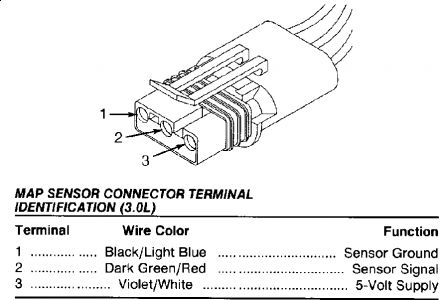
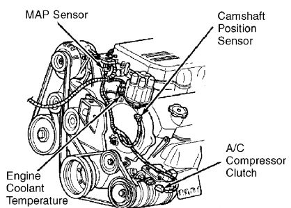
TEST TC-60A - BAROMETRIC PRESSURE OUT OF RANGE 1. Turn ignition on. Using scan tool, read MAP sensor voltage. If MAP sensor voltage is less than 2.2 volts, go to step 6). If MAP sensor voltage is 2.2 volts or more, go to next step. 2. Conditions required to set DTC are not present at this time. The MAP sensor voltage is used by Powertrain Control Module (PCM) to determine barometric pressure in the intake manifold. DTC may be stored in PCM when PCM senses MAP sensor voltage is less than 2.196 volts, but greater than .019 volt for 300 milliseconds. Go to next step. 3. Check for defective wiring or connections at MAP sensor and PCM. The PCM located between driver's side front fender and power distribution center, near battery. See MAP SENSOR LOCATION table. 4. If defective wiring or connections exist, repair as necessary. Perform TEST VER-2A . If no defective wiring or connections exist, go to next step. 5. Wiggle wiring harness and connector from MAP sensor to PCM while monitoring MAP sensor voltage. If MAP sensor voltage decreases to less than 2.2 volts while moving wiring harness, repair wiring harness or connector as necessary. Perform TEST VER-2A . If MAP sensor voltage does not decrease to less than 2.2 volts while moving wiring harness, see INACTIVE TROUBLE CODE CONDITION . 6. Disconnect connector at MAP sensor. See the MAP SENSOR LOCATION table. 7. Using scan tool, read MAP sensor voltage. If MAP sensor voltage more than 4.9 volts, replace MAP sensor. Perform TEST VER-2A . If MAP sensor voltage is 4.9 volts or less, go to next step. 8. If MAP sensor voltage is more than 2.2 volts, repair partial short to ground in Dark Green/Red wire between PCM and MAP sensor. Perform TEST VER-2A . The PCM is located between driver's side front fender and power distribution center, near battery. If MAP sensor voltage is 2.2 volts or less, go to next step. 9. Using scan tool in voltmeter mode, check voltage at Violet/White wire on connector for MAP sensor. If voltage is more than 4.5 volts, go to next step. If voltage is 4.5 volts or less, go to step 12). 10. Ensure ignition is off. Disconnect connectors from Powertrain Control Module (PCM). The PCM is located between driver's side front fender and power distribution center, near battery. 11. Using external ohmmeter, check resistance between Dark Green/Red wire on connector for MAP sensor and PCM connector terminal No. 36 (Dark Green/Red wire). If resistance is less than 5 ohms, replace PCM. Perform TEST VER-2A . If resistance is 5 ohms or more, repair open circuit in Dark Green/Red wire between PCM and MAP sensor. Perform TEST VER- 2A . 12. Turn ignition off. Disconnect connectors from Powertrain Control Module (PCM). The PCM is located between driver's side front fender and power distribution center, near battery. 13. Using scan tool in ohmmeter mode, check resistance at PCM connector terminal No. 61 (Violet/White wire). If resistance is less than 5 ohms, repair short to ground in Violet/White wire between PCM and MAP sensor. Perform TEST VER-2A . If resistance is 5 ohms or more, go to next step. NOTE: For connector terminal ID, see the CONNECTOR IDENTIFICATION DIRECTORY . For wiring diagram, see WIRING DIAGRAMS - 3.0L article.14. Using external ohmmeter, check resistance between Violet/White wire on connector for MAP sensor and PCM connector terminal No. 61 (Violet/White wire). If resistance is 5 ohms or more, repair open circuit in Violet/White wire between PCM and MAP sensor. Perform TEST VER-2A . If resistance is less than 5 ohms, replace PCM. Perform TEST VER-2A .


At least see if you can seperate the connector from the sensor, inspect for damaged pins. Reconnect it and see if it helps.
Monday, September 21st, 2020 AT 12:59 PM


