Good evening,
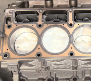
I attached the procedure and pictures for you of the process for replacing the head gasket.
I would have a leak down test done to confirm to be sure it is the issue.
Roy
303-01A Engine - 2.3L EcoBoost (231kW/314PS) 2018 Mustang
Removal and Installation
Cylinder Head
Base Part Number: 6051
Special Tool(s) / General Equipment
Oil Drain Equipment
Hose Clamp Remover/Installer
Removal
NOTICE: Do not loosen or remove the crankshaft pulley bolt without first installing the special tools as instructed in this procedure. The crankshaft pulley and the crankshaft timing sprocket are not keyed to the crankshaft. The crankshaft, the crankshaft sprocket and the pulley are fitted together by friction. For that reason, the crankshaft sprocket is also unfastened if the pulley bolt is loosened. Before any repair requiring loosening or removal of the crankshaft pulley bolt, the crankshaft and camshafts must be locked in place by the special service tools, otherwise severe engine damage can occur.
NOTICE: During engine repair procedures, cleanliness is extremely important. All parts must be thoroughly cleaned and any foreign material, including any material created while cleaning gasket surfaces, that enters the oil passages, coolant passages or the oil pan, can cause engine failure.
With the vehicle in NEUTRAL, position it on a hoist.
Refer to: Jacking and Lifting - Overview (100-02 Jacking and Lifting, Description and Operation).
Remove the nuts and the engine appearance cover.
Image
Release the fuel system pressure.
Refer to: Fuel System Pressure Release (310-00A Fuel System - General Information - 2.3L EcoBoost (231kW/314PS), General Procedures).
Disconnect the battery ground.
Refer to: Battery Disconnect and Connect (414-01 Battery, Mounting and Cables, General Procedures).
Drain the cooling system.
Refer to: Cooling System Draining, Vacuum Filling and Bleeding (303-03A Engine Cooling - 2.3L EcoBoost (231kW/314PS), General Procedures).
Remove the following items:
Remove the turbocharger.
Refer to: Turbocharger (303-04D Fuel Charging and Controls - Turbocharger - 2.3L EcoBoost (231kW/314PS), Removal and Installation).
Remove the intake manifold.
Refer to: Intake Manifold (303-01A Engine - 2.3L EcoBoost (231kW/314PS), Removal and Installation).
Remove the camshafts.
Refer to: Camshafts (303-01A Engine - 2.3L EcoBoost (231kW/314PS), Removal and Installation).
NOTE: If the valve tappets are to be reused, note the location of the valve tappets to make sure they are assembled in their original positions.
Remove the valve tappets.
ImageOpen In New TabZoom/Print
Detach and disconnect the fuel rail electrical connector.
Detach the wiring harness retainers.
Remove the fuel rail insulator shield.
Image
Disconnect and position the coolant tube aside.
Use the General Equipment: Hose Clamp Remover/Installer
imageOpen In New TabZoom/Print
Disconnect the fuel injector and the FRP sensor electrical connectors.
Image
Disconnect the ECT sensor electrical connector from the back of the engine.
ImageOpen In New TabZoom/Print
Disconnect the crankcase vent tube sensor electrical connector and wire harness retainer.
Detach the crankcase vent tube retainer and remove.
Image
Disconnect the upper radiator hose from the coolant outlet tube.
Use the General Equipment: Hose Clamp Remover/Installer
Disconnect the coolant by-pass hose from the degas bottle.
Use the General Equipment: Hose Clamp Remover/Installer
imageOpen In New TabZoom/Print
Remove the bolt from the cylinder head and remove the coolant tube from coolant outlet.
Image
Remove and discard the coolant tube O-ring seal.
ImageOpen In New TabZoom/Print
Slide the insulator up and disconnect the CHT sensor electrical connector.
Image
Remove the bolts and the coolant tube.
ImageOpen In New TabZoom/Print
Inspect the coolant tube O-ring seal and replace if necessary.
Image
Remove the bolt and the ground wire.
ImageOpen In New TabZoom/Print
Disconnect the heater hose from the coolant outlet.
Use the General Equipment: Hose Clamp Remover/Installer
image
Remove the bolts and the cylinder head.
Discard the bolts.
ImageOpen In New TabZoom/Print
Remove and discard the cylinder head gasket.
Image
NOTICE: Do not use metal scrapers, wire brushes, power abrasive discs or other abrasive means to clean the sealing surfaces. These tools cause scratches and gouges that make leak paths. Use a plastic scraping tool to remove all traces of the head gasket.
NOTE: Clean the cylinder head bolt holes in the cylinder block. Make sure all coolant, oil or other foreign material is removed.
Make sure that the mating faces are clean and free of foreign material.
ImageOpen In New TabZoom/Print
Check the cylinder head distortion.
Refer to: Cylinder Head Distortion (303-00 Engine System - General Information, General Procedures).
Check the cylinder block distortion.
Refer to: Cylinder Block Distortion (303-00 Engine System - General Information, General Procedures).
Installation
Install the cylinder head gasket.
Image
NOTE: The cylinder head bolts are torque-to-yield and must not be reused. New cylinder head bolts must be installed.
Install the cylinder head and the new bolts.
Torque :
Stage 1: 62 lb. In (7 Nm)
Stage 2: 133 lb. In (15 Nm)
Stage 3: 41 lb. Ft (55 Nm)
Stage 4: 90°
Stage 5: 90°
Images (Click to make bigger)
Tuesday, December 1st, 2020 AT 2:20 PM


