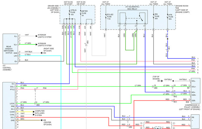
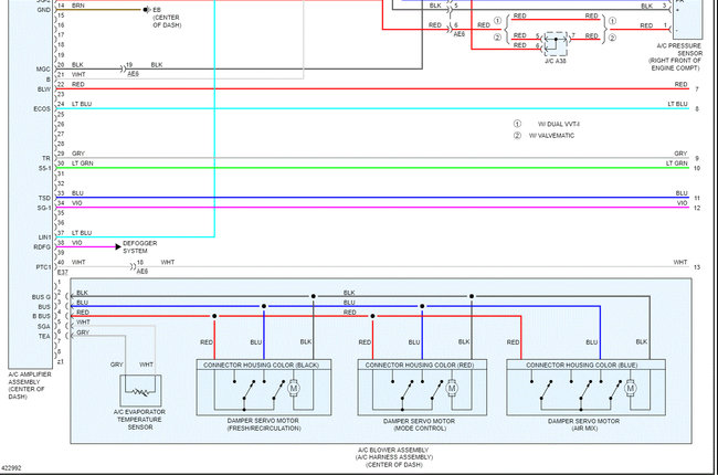
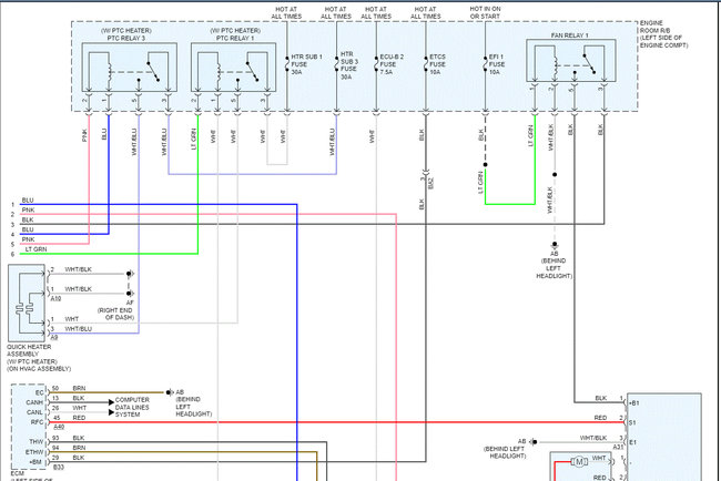
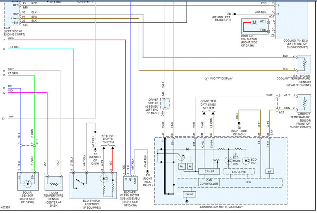
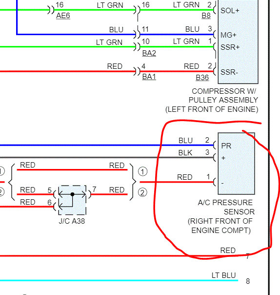
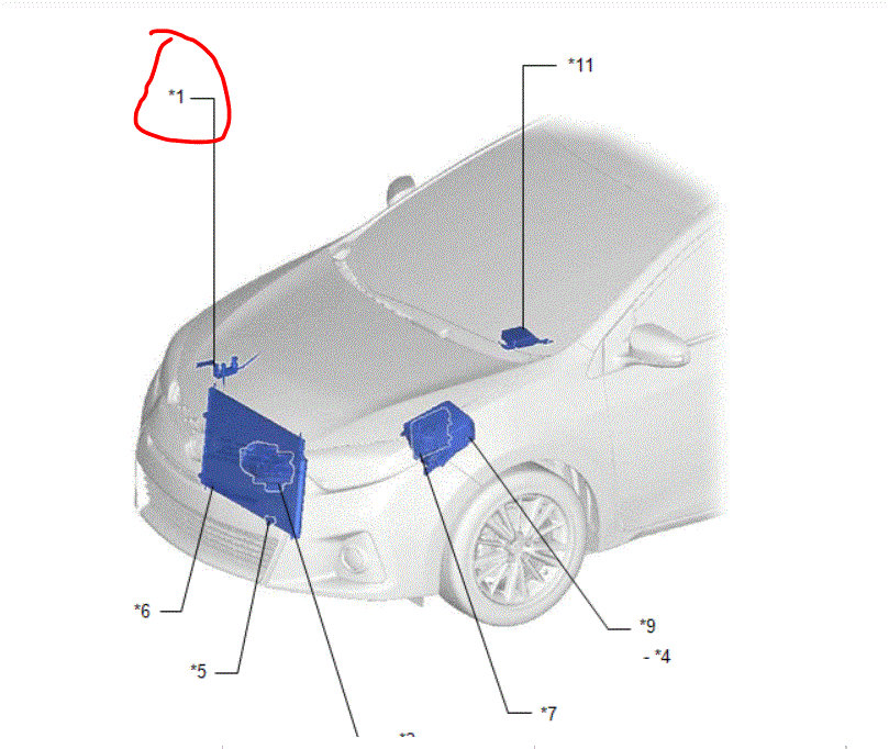
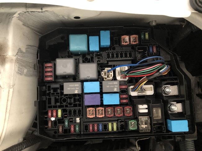
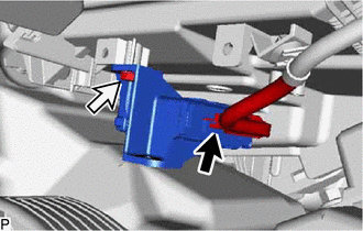
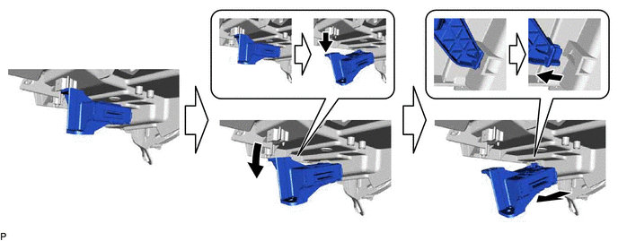
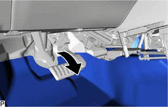
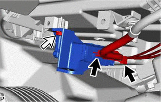
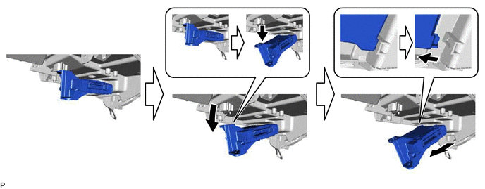
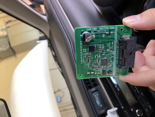
Okay. The static pressure sounds good. As far as where to check for power, I am going to provide a diagnostic flow chart. The attached pics correlate with the directions. Also, it explains what, how, and the specs for checking. The directions will refer to an MGC relay. That is basically the compressor relay which is powered by the ignition 1 relay in the under hood fuse/relay box.
________________________________
2014 Toyota Corolla L4-1.8L (2ZR-FAE)
Air Conditioning System (Automatic Air Conditioning System) - Air Conditioning Compressor Magnetic Clutch Circuit [08/2013 - ]
Air Conditioning Compressor Magnetic Clutch Circuit
DESCRIPTION
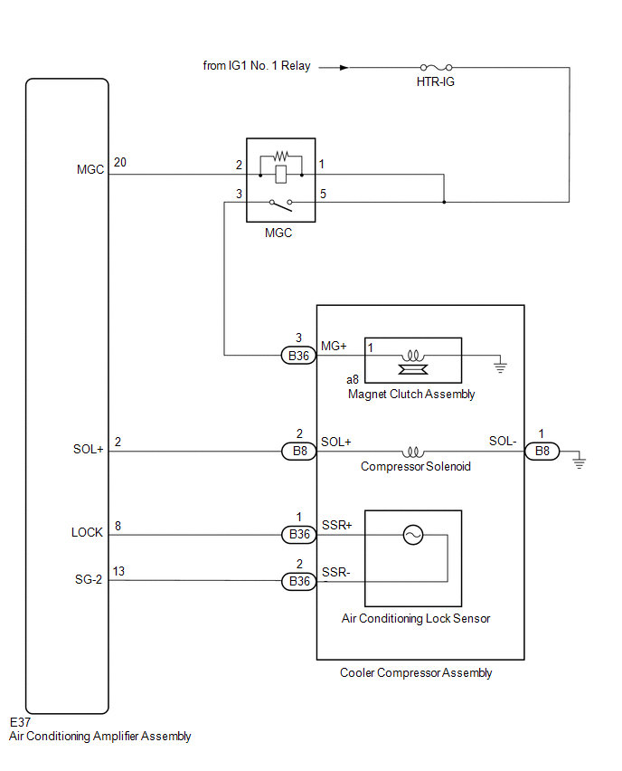
When the air conditioning amplifier assembly is turned on, a magnet clutch on signal is sent from the MGC terminal of the air conditioning amplifier assembly. Then, the MGC relay turns on to operate the magnet clutch assembly.
WIRING DIAGRAM
pic 1
CAUTION / NOTICE / HINT
NOTICE:
ECM malfunctions can affect the storage of this DTC. Therefore, check all EFI system DTCs and confirm that the system is normal before performing the following inspection.
Click here [ 2ZR-FAE (ENGINE CONTROL): SFI SYSTEM: DTC CHECK / CLEAR ]
Inspect the fuses for circuits related to this system before performing the following procedure.
PROCEDURE
1. INSPECT MGC RELAY
Remove the MGC relay.
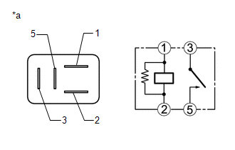
Measure the resistance according to the value(s) in the table below.
Standard Resistance:
Tester Connection Condition Specified Condition
3 - 5 Battery voltage not applied between terminals 1 and 2 10 or higher
3 - 5 Battery voltage applied between terminals 1 and 2 Below 1
pic 2
a Component without harness connected
(MGC Relay)
Result:
Proceed to
OK
NG
NG -- REPLACE MGC RELAY
OK -- Continue to next step.
2. CHECK HARNESS AND CONNECTOR (MGC RELAY - POWER SOURCE)
Measure the voltage according to the value(s) in the table below.
Standard Voltage:
Tester Connection Condition Specified Condition
Relay terminal 5 - Body ground Ignition switch off Below 1 V
Relay terminal 5 - Body ground Ignition switch ON 11 to 14 V
Relay terminal 1 - Body ground Ignition switch off Below 1 V
Relay terminal 1 - Body ground Ignition switch ON 11 to 14 V
Result:
Proceed to
OK
NG
NG -- REPAIR OR REPLACE HARNESS OR CONNECTOR
OK -- Continue to next step.
3. CHECK HARNESS AND CONNECTOR (MGC RELAY - COOLER COMPRESSOR ASSEMBLY)
Disconnect the B36 cooler compressor assembly connector.
Measure the resistance according to the value(s) in the table below.
Standard Resistance:
Tester Connection Condition Specified Condition
Relay terminal 3 - B36-3 (MG+) Always Below 1
Relay terminal 3 - Body ground Always 10 k or higher
Result:
Proceed to
OK
NG
NG -- REPAIR OR REPLACE HARNESS OR CONNECTOR
OK -- Continue to next step.
4. CHECK HARNESS AND CONNECTOR (MGC RELAY - AIR CONDITIONING AMPLIFIER ASSEMBLY)
Disconnect the E37 air conditioning amplifier assembly connector.
Measure the resistance according to the value(s) in the table below.
Standard Resistance:
Tester Connection Condition Specified Condition
Relay terminal 2 - E37-20 (MGC) Always Below 1
Relay terminal 2 - Body ground Always 10 k or higher
Result:
Proceed to
OK
NG
NG -- REPAIR OR REPLACE HARNESS OR CONNECTOR
OK -- Continue to next step.
5. CHECK MAGNET CLUTCH ASSEMBLY
Disconnect the B36 cooler compressor assembly connector.
Measure the resistance according to the value(s) in the table below.
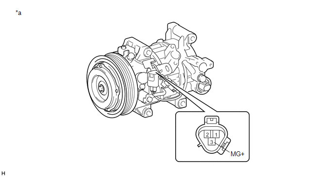
Pic 3
a Component without harness connected
(Cooler Compressor Assembly) - -
Standard Resistance:
Tester Connection Condition Specified Condition
3 (MG+) - Body ground 20°C (68°F) 3.8 to 4.2
Connect a positive (+) lead from the battery to terminal 3 (MG+) and check that the following occurs: 1) the magnet clutch assembly operating sound can be heard, and 2) the magnet clutch hub and rotor lock.
OK:
1) The magnet clutch assembly operating sound can be heard, and 2) the magnet clutch hub and rotor lock.
Result:
Proceed to
OK
NG
OK -- PROCEED TO NEXT SUSPECTED AREA SHOWN IN PROBLEM SYMPTOMS TABLE [ HEATING / AIR CONDITIONING: AIR CONDITIONING SYSTEM(for Automatic Air Conditioning System): PROBLEM SYMPTOMS TABLE ]
NG -- REPLACE MAGNET CLUTCH ASSEMBLY [ HEATING / AIR CONDITIONING: COMPRESSOR(for 2ZR-FAE): DISASSEMBLY ]
_____________________
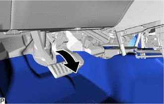
If you look at pic 4, it shows the location of the AC pressure sensor.
Let me know if this helps.
Joe
Images (Click to make bigger)
Friday, March 27th, 2020 AT 8:46 PM
