WITHOUT AIRBAG
The following procedure requires the use of the GM Lock Plate Compressor tool No. J-23653 or equivalent.
1. Disconnect the negative battery cable.
2. Remove the steering wheel.
3. If necessary, remove the steering column-to-lower instrument panel cover. Disengage the electrical harness connector from the steering column jacket (under the dash).
4. Using a small prytool, insert into the slots between the steering shaft lock plate cover and the steering column housing, then pry upward to remove the cover from the lock plate.
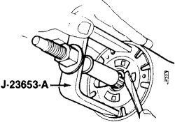
5. Using the GM Lock Plate Compressor tool No. J-23653 or equivalent, screw the center shaft onto the steering shaft (as far as it will go), then screw the center post nut clockwise until the lock plate is compressed.
6. Using a small prybar, carefully pry the snapring from the steering shaft slot.
If the steering column is being disassembled on a bench, the steering shaft will slide out of the mast jacket when the snapring is removed.
7. Remove the GM Lock Plate Compressor tool No. J-23653 or equivalent, and the lock plate.
8. Remove the multi-function lever-to-switch screw and the lever.
9. To remove the hazard warning switch, press the knob inward and unscrew it.
10. Remove the turn signal switch assembly-to-steering column screws.
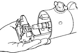
11. Lift the turn signal switch assembly from the steering column, then slide the electrical connector through the column housing and the protector.
If the steering column is the tilting type, position the steering housing into the Low position.
12. To remove the harness cover, pull it toward the lower end of the column; be careful not to damage the wires.
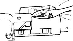
13. To remove the wire protector, grab the protector's tab with a pair of pliers, then pull the protector downward, out of the steering column.
When assembling the steering column, use only fasteners of the correct length; overlength fasteners could prevent a portion of the assembly from compressing under impact.
To install:
14. Install the turn signal switch electrical connector:
A. On the non-tilt columns, be sure the electrical connector is on the protector, then feed it and the cover down through the housing and under the mounting bracket.
B. On the tilt columns, feed the electrical connector down through the housing and under the mounting bracket, then install the cover onto the housing.
15. Install the electrical connector to the clip on the jacket, the turn signal switch-to-steering column mounting screws, the lower instrument trim panel, the turn signal lever/screws and the hazard warning knob.
With the multi-function lever installed, place it into the Neutral position. With the hazard warning knob installed, pull it outward.
16. Onto the upper end of the steering shaft, install the washer, the upper bearing preload spring, the canceling cam, the lock plate and a new retaining ring (snapring). Using the GM Lock Plate Compressor tool No. J-23653 or equivalent, compress the lock plate and slide the new retaining ring into the steering shaft groove.
17. Tighten the multi-function switch-to-steering column screws to 35 inch lbs. (4 Nm) and the steering wheel nut to 30 ft. Lbs. (41 Nm).
18. Connect the negative battery cable and check operation.
SPONSORED LINKS
Saturday, May 15th, 2010 AT 10:05 PM
