XTooltipElement
Service Information
2003 Chevrolet Tahoe - 4WD | Avalanche, Escalade, Suburban, Tahoe, Yukon (VIN C/K) Service Manual | Suspension | Front Suspension | Repair Instructions | Document ID: 875921
Front Wheel Hub, Bearing, and Seal Replacement (4WD)
Tools Required
J 45859 Axle Remover
Removal Procedure
Raise and support the vehicle. Refer to Lifting and Jacking the Vehicle .
Remove the tire and wheel. Refer to Tire and Wheel Removal and Installation .
Remove the rotor. Refer to Front Brake Rotor Replacement .
Remove the wheel speed sensor and brake hose mounting bracket bolt from the steering knuckle.
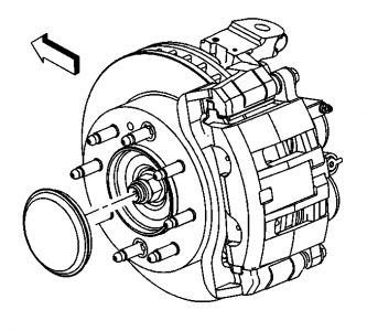
Remove the wheel drive shaft nut retaining cover.
Important: Do not reuse the nut. A new nut must be used when installing the wheel drive shaft.
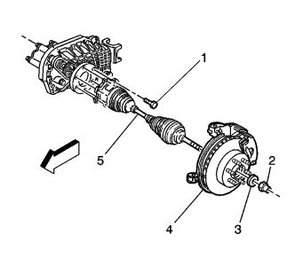
Remove the wheel driveshaft assembly retaining nut (2) and washer (3) from the wheel driveshaft.
Disengage the wheel drive shaft from the wheel hub and bearing using J 45859 or equivalent.
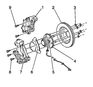
Remove the wheel hub (4) and the 15-series bearing mounting bolts (9).
Notice: Wheel drive shaft boots, seals and clamps should be protected from sharp objects any time service is performed on or near the wheel drive shaft(s). Damage to the boot(s), the seal(s) or the clamp(s) may cause lubricant to leak from the joint and lead to increased noise and possible failure of the wheel drive shaft.
Wrap shop towels around the inner and outer wheel drive shaft boots.
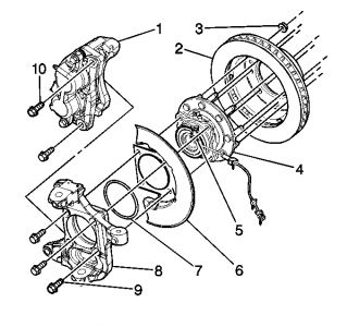
Remove the wheel hub and bearing (4) mounting bolts, 25/35 series.
Remove the wheel hub and bearing and splash shield from the vehicle.
Remove the O-ring seal from the steering knuckle bore, 25/35 series.
Remove the wheel speed sensor mounting bolt (5).
Clean and inspect the O-ring seal, 25/35 series.
Replace the seal if the following conditions exist:
"� Nicks
"� Cuts
"� Dry or brittle
"� Compression set
Installation Procedure
Clean all corrosion or contaminates from the steering knuckle bore and the hub and bearing assembly.
Lubricate the steering knuckle bore with wheel bearing grease or the equivalent.
Install the O-ring (7) to the steering knuckle, the 25/35 series.
Notice: Use the correct fastener in the correct location. Replacement fasteners must be the correct part number for that application. Fasteners requiring replacement or fasteners requiring the use of thread locking compound or sealant are identified in the service procedure. Do not use paints, lubricants, or corrosion inhibitors on fasteners or fastener joint surfaces unless specified. These coatings affect fastener torque and joint clamping force and may damage the fastener. Use the correct tightening sequence and specifications when installing fasteners in order to avoid damage to parts and systems.
Install the wheel speed sensor mounting bolt to the wheel hub and bearing.
Tighten
Tighten the sensor mounting bolt to 18 N � m (13 lb ft).
Install the wheel hub and bearing and splash shield to the vehicle, 25/35 series.
Install the wheel hub and bearing (5) and splash shield (6) to the vehicle, 15 series.
Install the wheel hub and bearing mounting bolts (8), the 15 series.
Install the wheel hub and bearing mounting bolts (8), 25/35 series.
Tighten
Tighten the wheel hub to knuckle bolts to 180 N � m (133 lb ft).
Install the nut (2) and washer (3) retaining the wheel drive shaft assembly to the wheel hub and bearing.
Tighten
Tighten the nut to 240 N � m (177 lb ft).
Install the wheel speed sensor and brake hose mounting bracket bolt to the steering knuckle.
Tighten
Tighten the brake hose clip bolt to 12 N � m (106 lb in).
Install the rotor. Refer to Front Brake Rotor Replacement .
Install the tire and wheel. Refer to Tire and Wheel Removal and Installation .
Lower the vehicle .
© 2008 General Motors Corporation. All rights reserved.


Saturday, November 15th, 2008 AT 8:43 AM


