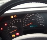
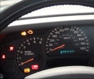
Hi,
It could be the BCM, but the code could mean a few things. The CAN system (controller area network) could be the issue as well. If you look below at pic 1, it shows the possible causes for this code to set.
To determine the cause requires a good bit of diagnostic work. I will add the diagnostics for your review. Let me know if this is something you are comfortable doing and if you have the tooling.
_________________________________________
1. VERIFY DTC IS ACTIVE
NOTE: Make sure the battery voltage is between 10 and 16 volts before proceeding.
1. With the scan tool, read active DTCs.
Is this DTC active?
Yes
- Go To 2
No
- See: A L L Diagnostic Trouble Codes ( DTC ) > Manufacturer Code Charts > Stored Lost Communication DTCs Perform the STORED LOST COMMUNICATION DTCS diagnostic procedure.
2. CHECK FOR ANY OF THE FOLLOWING ACTIVE DTCS
1. With the scan tool, read active DTCs from all modules.
NOTE: Check for BCM configuration, CAN Interior Bus hardware electrical, VIN Missing/Mismatch, battery or ignition related DTCs.
Does the scan tool display any active DTCs to the conditions listed above?
Yes
- Go to and perform the appropriate diagnostic procedure.
No
- Go To 3
3. VERIFY THE VSIM IS ACTIVE ON THE BUS
1. Turn the ignition on.
2. With the scan tool, verify the VSIM is active on the bus.
Is the VSIM active on the bus?
Yes
- Go To 4
No
- See: A L L Diagnostic Trouble Codes ( DTC ) > Manufacturer Code Charts > Communications - Verbose Codes and perform the NO RESPONSE FROM VSIM diagnostic procedure.
4. CHECK FOR ADDITIONAL COMMUNICATION RELATED DTCS
1. With the scan tool, read all the DTCs.
Is there more than one module with active DTCs "Logged Against" the VSIM?
Yes
- Replace/update the Vehicle System Interface Module. See: Signal Processing Module > Removal and Replacement > Vehicle System Interface Module - Removal.
- Perform the BODY VERIFICATION TEST. See: A L L Diagnostic Trouble Codes ( DTC ) > Verification Tests > Body Verification Test.
No
- Go To 5
5. CLEAR DTC IN MODULE SETTING FAULT
1. With the scan tool, select the module setting the DTC against the VSIM.
2. Clear active DTCs.
Is this DTC still active?
Yes
- Replace/update the module that set this DTC.
- Perform the appropriate verification test for the module being replaced See: A L L Diagnostic Trouble Codes ( DTC ) > Verification Tests. If there is no verification test for the associated module perform the BODY VERIFICATION TEST. See: A L L Diagnostic Trouble Codes ( DTC ) > Verification Tests > Body Verification Test.
No
- Go To 6
6. CYCLE IGNITION
1. Cycle the ignition from RUN to OFF three times ending with the key in the RUN position.
Does this DTC become active?
Yes
- Go To 7
No
- The condition is not present at this time. Using the wiring diagrams as a guide, check all related splices and connectors for signs of water intrusion, corrosion, pushed out or bent terminals, and correct pin tension.
- Perform the appropriate verification test for the module See: A L L Diagnostic Trouble Codes ( DTC ) > Verification Tests. If there is no verification test for the associated module perform the BODY VERIFICATION TEST. See: A L L Diagnostic Trouble Codes ( DTC ) > Verification Tests > Body Verification Test.
7. CHECK FOR ADDITIONAL LOST COMMUNICATION FAULTS
1. With the scan tool, read the DTCs.
Does the BCM and other CAN IHS BUS modules show Lost Communication with the remaining CAN IHS BUS modules?
Yes
- Go To 8
No
- Replace/update the module that set this DTC.
- Perform the appropriate verification test for the module being replaced See: A L L Diagnostic Trouble Codes ( DTC ) > Verification Tests. If there is no verification test for the associated module perform the BODY VERIFICATION TEST. See: A L L Diagnostic Trouble Codes ( DTC ) > Verification Tests > Body Verification Test.
8. CHECK THE (D265) CAN IHS BUS (125K) (+) CIRCUIT FOR A SHORT TO VOLTAGE
imageOpen In New TabZoom/Print
1. Measure the voltage between the (D265) CAN IHS Bus (125K) (+) circuit and ground.
Is the voltage above 5.0 volts?
Yes
- Repair the short to voltage in the (D265) CAN IHS Bus (125K) (+) circuit. The short to voltage is present in one of the CAN IHS Bus (125K) (+) circuits. Use the Star Connectors to isolate portions of the CAN IHS Bus (125K) (+) in order to locate the concern.
- Perform the BODY VERIFICATION TEST. See: A L L Diagnostic Trouble Codes ( DTC ) > Verification Tests > Body Verification Test.
No
- Go To 9
9. CHECK THE (D264) CAN IHS BUS (125K) (-) CIRCUIT FOR A SHORT TO GROUND
imageOpen In New TabZoom/Print
1. Turn the ignition off.
2. Measure the resistance between ground and the (D264) CAN IHS Bus (125K) (-) circuit.
Is the resistance below 10k Ohms?
Yes
- Repair the short to ground in the (D264) CAN IHS Bus (125K) (-) circuit. The short to ground is present in one of the CAN IHS Bus (125K) (-) circuits. Use the Star Connectors to isolate portions of the CAN IHS Bus (125K) (-) in order to locate the concern.
- Perform the BODY VERIFICATION TEST. See: A L L Diagnostic Trouble Codes ( DTC ) > Verification Tests > Body Verification Test.
No
- Replace/update the module that set this DTC.
- Perform the appropriate verification test for the module being replaced See: A L L Diagnostic Trouble Codes ( DTC ) > Verification Tests. If there is no verification test for the associated module perform the BODY VERIFICATION TEST. See: A L L Diagnostic Trouble Codes ( DTC ) > Verification Tests > Body Verification Test.
_________________________________________
I will watch for your reply.
Take care,
Joe
Image (Click to make bigger)
Wednesday, March 3rd, 2021 AT 5:15 PM


