Car not starting

2005 HYUNDAI ACCENT
130,000 MILES • 1.6L • 4 CYL • 2WD • MANUAL
Avatar
A0302
  • MEMBER
  • 62 POSTS
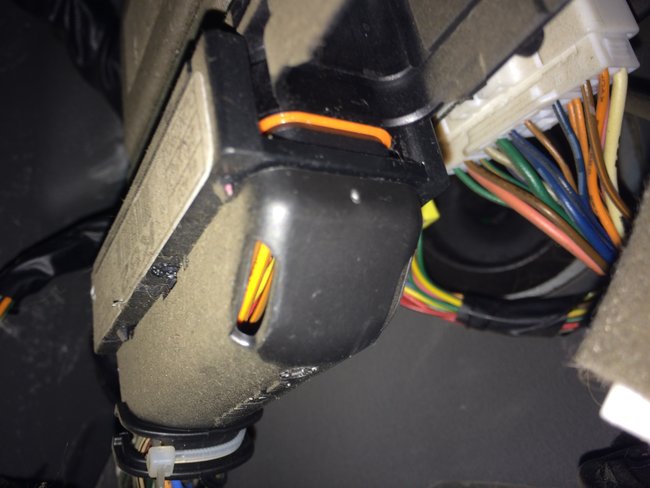
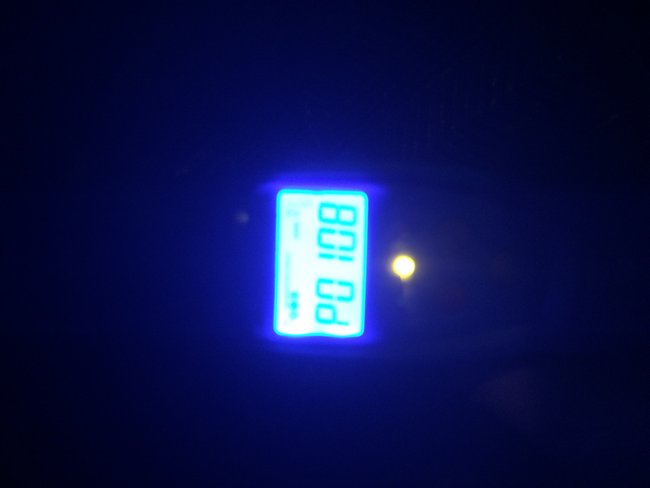
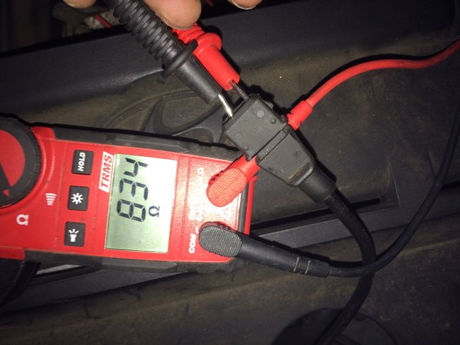
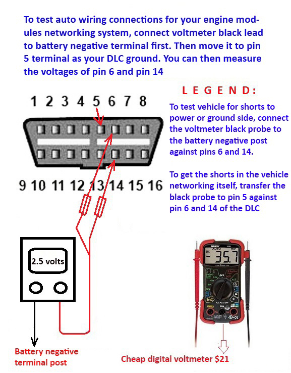
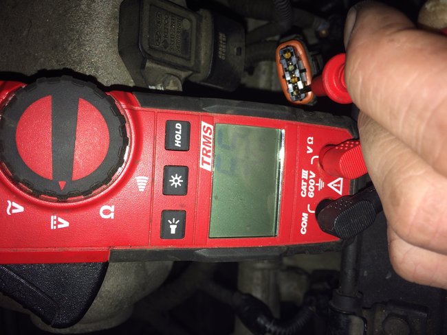
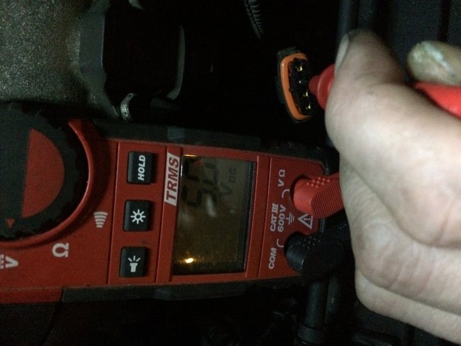
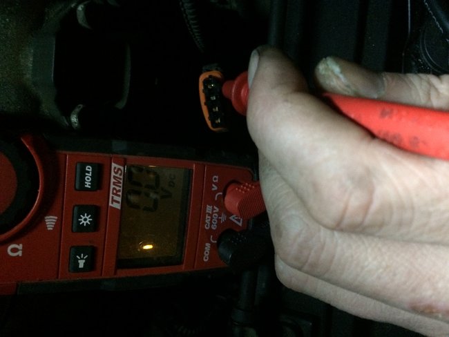
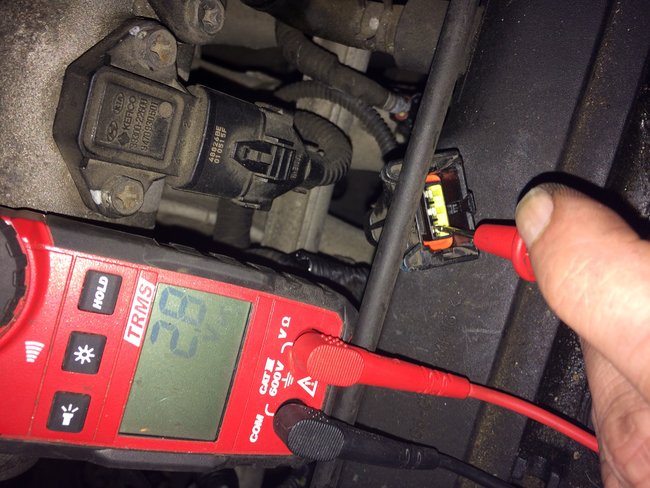
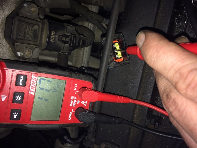
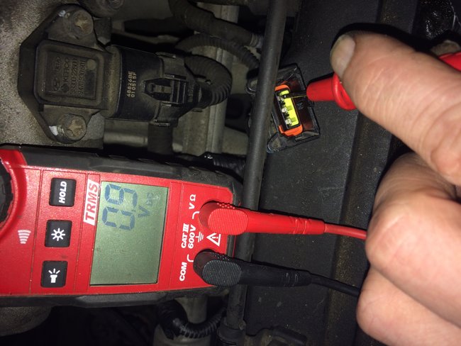
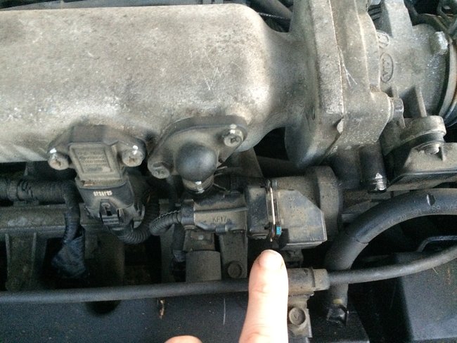
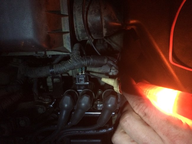
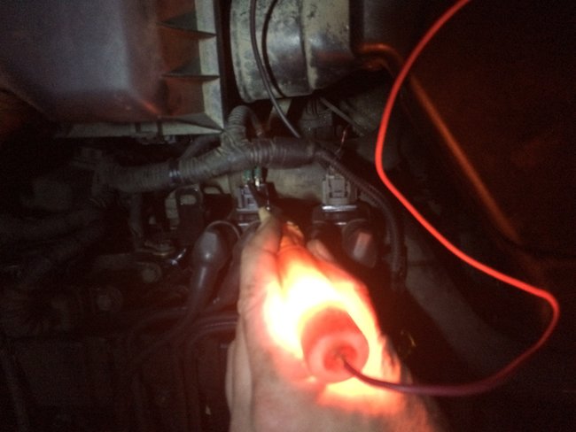
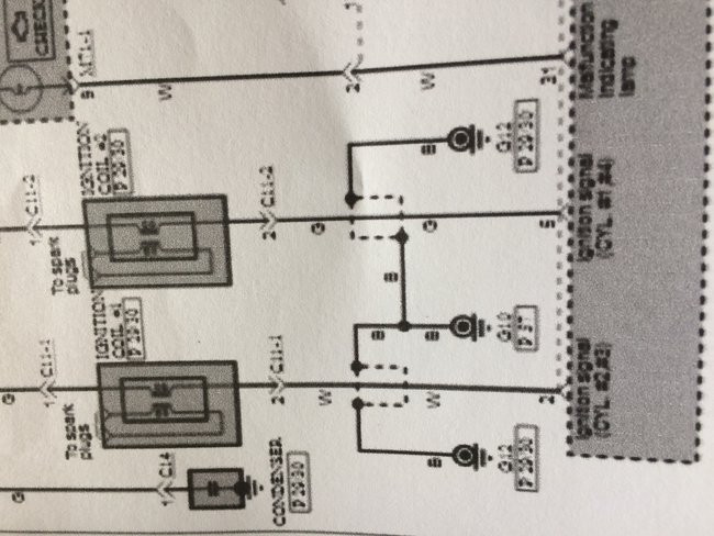
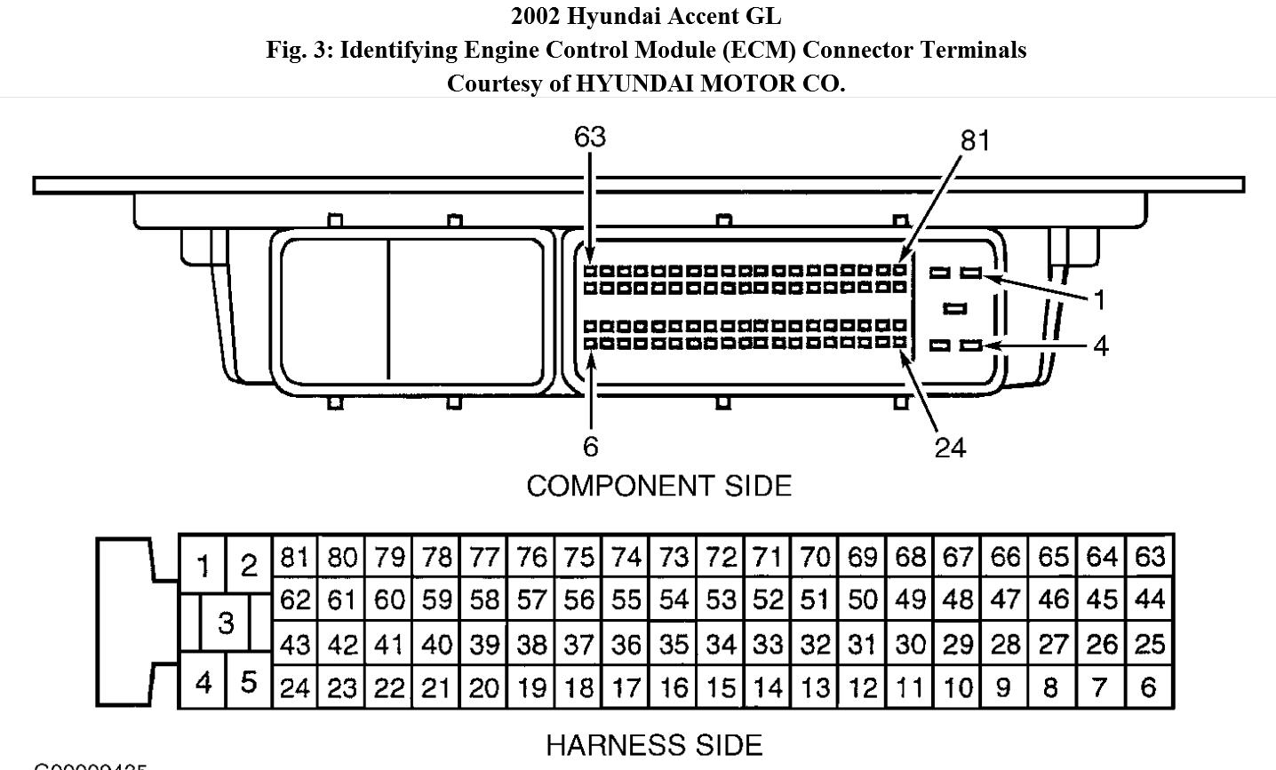
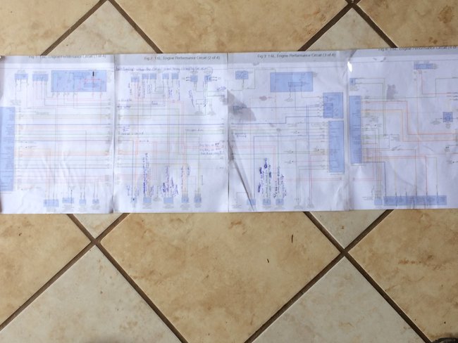
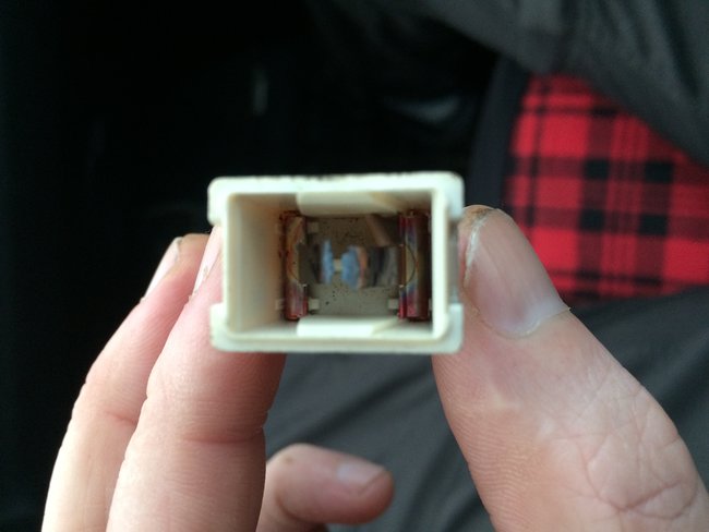
Car is not starting due to accidentally being jump started with leads reversed. Coil was replaced as it fried. New coil is in but no spark and also no injector pulse. Power is going to coil and injection plugs. Crank sensor shows 800 ohms and AC voltage is 1.15 volts when cranked and .017 volts without cranking. All fuses are good. Not sure if crank sensor is the problem? Battery is fully charged. Also, tested crank sensor by tapping on plug terminals with key on and using test light on battery positive to send 12 volts to switch to get a relay click and nothing happened. Could computer be tested at the harness plug and check for voltage to see if it is switching to o volts for signal? Any feedback would be appreciated.
May 3, 2018 at 9:04 PM
Advertisement
Avatar
STRAILER
  • CERTIFIED EXPERT
  • 53,855 POSTS
The crankshaft sensor sounds like it is okay can you run the codes to see what comes up?

https://www.2carpros.com/articles/checking-a-service-engine-soon-or-check-engine-light-on-or-flashing

Also, the PCM really does not like it when the voltage is reversed. There is a 20 amp fusible link that I would check as well. Here are the engine wiring diagrams so we can do some testing and see how the system works:

https://www.2carpros.com/articles/how-to-use-a-test-light-circuit-tester

Check power and grounds. Check out the diagrams (below). Please let us know what happens.

Cheers, Ken
May 15, 2018 at 12:07 PM
Avatar
A0302
  • MEMBER
  • 62 POSTS
Thank you Ken. I will go through diagrams and see if I can get a code with my reader. Just wanted to mention I tried a crank sensor but no go. The resistance reading I found for the car is to be .46-.58 kilo ohms for crank sensor. The sensor was .82 for the one I took out. Would this cause issues for this? Also, the crank sensor is only two wires on mine not three as in your diagrams. Not sure if we need a different diagram to trouble shoot electrical?
May 15, 2018 at 4:17 PM
Advertisement
Avatar
STRAILER
  • CERTIFIED EXPERT
  • 53,855 POSTS
I see two wires on the crankshaft sensor. First diagram, sensor on the lower part of the wiring diagram.
May 15, 2018 at 5:54 PM
Avatar
A0302
  • MEMBER
  • 62 POSTS
Okay, I managed to get a p0108 code. MAP sensor. Tested sensor plug for power with key on and got the results.
May 17, 2018 at 12:05 PM
Avatar
A0302
  • MEMBER
  • 62 POSTS
Sorry wrong pictures. That was for 02 sensor. The plug from map sensor(4pins) 1st pin 5.5 volts 2nd pin 5.0 volts . 3rd pin 5.0 volts. 4th pin 0 volts. Question? The 5 volt reading is 5 volt reference from PCM? Meaning good PCM? Also, in picture ECM would I take black harness cover off to access pin testing for ECM?
May 17, 2018 at 12:24 PM
Avatar
A0302
  • MEMBER
  • 62 POSTS
The 834 ohms test was on the crank sensor. It is over the amount specified by 200 ohms. Could this be the problem?
May 17, 2018 at 12:36 PM
Avatar
STRAILER
  • CERTIFIED EXPERT
  • 53,855 POSTS
Yes you do remove the black plastic to run a pin to pin test or just undo the connector. Also, that Ohms reading on the crankshaft sensor does not look good to me. Here is a guide to help you see what you are in for when doing the job:

https://www.2carpros.com/articles/crankshaft-angle-sensor-replacement

Here is the location for others visiting this post.

Check out the diagrams (below). Please let us know what happens.

Cheers, Ken
May 18, 2018 at 9:40 AM
Avatar
A0302
  • MEMBER
  • 62 POSTS
Okay thanks Ken. I actually replaced crank sensor before hand and new one had 900 ohms or .90 kilo ohms of resistance. Higher than old one. The sensor was easy enough to do on this 2005 accent as long as someone has a 1/4” ratchet and 4-6” extension with a universal joint and 10 mm socket. Did not have to jack up vehicle or take anything off to access it. I had to use a long 15” skinny bar to tap onto the top corner of sensor few times carefully to free it up and then wiggle it to get out. The o-ring was stuck inside and used a small screwdriver to pull out.The second crank sensor is on its way and will let you know how it goes.
May 18, 2018 at 11:34 AM
Avatar
A0302
  • MEMBER
  • 62 POSTS
Before I checked for computer grounds and positives I found some useful information on a site regarding using cars dlc obd connector for checking ground and ECM harness for shorts. See picture attached.could be helpful for anyone else as well.
May 18, 2018 at 11:40 AM
Avatar
STRAILER
  • CERTIFIED EXPERT
  • 53,855 POSTS
Nice! That is good information please let me know with the new sensor.
May 19, 2018 at 8:55 AM
Avatar
A0302
  • MEMBER
  • 62 POSTS
Hey ken thanks for your continued help with this. Your guide has helped a lot. The other issue on map sensor I was thinking about voltage readings I got as shown previously. There was two 5 volt readings. And one 5.5 volt reading. Would the .5 volts higher reading cause map sensor code to come up? As I thought there is a resistor or something in that circuit that will not allow higher than 5 volt to come from ECM.
May 20, 2018 at 2:03 PM
Avatar
STRAILER
  • CERTIFIED EXPERT
  • 53,855 POSTS
.5 volts should not matter that much. Does the car have spark, fuel and injector pulse?
May 21, 2018 at 9:42 AM
Avatar
A0302
  • MEMBER
  • 62 POSTS
No spark or injector pulse. Gets fuel and can here pump priming when key on and relay click off when ignition off. You and I suspected the crank position sensor previously. Waiting to put in another one. I was just curious about the MAP sensor code that only came up with vehicle issues. We have the five volt reference reading so PCM health is okay. It has been hard to diagnose with no proper codes showing crank sensor and after putting in a new sensor and finding its defective. I do not have a noid light but used a light tester on battery positive and checking for flashing on control side. To confirm I used a voltmeter to check if signal wire on injector was getting zero volts and did not.
May 21, 2018 at 10:56 AM
Avatar
STRAILER
  • CERTIFIED EXPERT
  • 53,855 POSTS
It sounds like the crankshaft sensor but can we confirm the camshaft timing is good does the engine sounds normal when cranking over? Does the engine have compression? A bad crankshaft sensor will not trigger a code only a circuit error will show.

https://www.2carpros.com/articles/how-to-test-engine-compression

Please let us know what you find.

Cheers, Ken
May 22, 2018 at 9:55 AM
Avatar
A0302
  • MEMBER
  • 62 POSTS
Yes car has good compression. All grounds are good too. Car ran perfect until it was jump started wrong. All sensors have their 5 volt ref and have 0 volts on the signal from PCM. I purchased a new scanner from eBay Foxwell nt301 that has live data stream and sensor checks etc. Hopefully this will narrow it down if new crank sensor is not it. Thanks again Ken.
May 22, 2018 at 10:26 AM
Avatar
A0302
  • MEMBER
  • 62 POSTS
Sorry Ken my last reply was not accurate as I found an issue with the TPS. I took volt readings on all three pins of TPS harness koeo and have .9 volts 11.7 volts And 2.8 volts. I reviewed the wiring diagrams you sent me on electrical from previous chats and the TPS is to have a 5 volt supply to it and as you can see there is not. See attachments. Also there is a loud humming sound coming from the throttle body where TPS bolts in. I unplugged it and it goes away but hums again when plugged in. Even though there is 5 volt ref to others like map sensor and not to TPS sensor, would that indicate faulty ECM now?
May 22, 2018 at 9:30 PM
Avatar
STRAILER
  • CERTIFIED EXPERT
  • 53,855 POSTS
Yes that is my thinking. If you have good power and ground to the PCM and you have checked all wiring connections it the only thing left.
May 23, 2018 at 10:44 AM
Avatar
A0302
  • MEMBER
  • 62 POSTS
Hi Ken, so I ended up putting in another crank sensor in and it did nothing but crank once again. The sensor had high ohms .89 kilo ohms. This is the second one now. I decided to put old sensor back in and still just cranks. I checked for pulse at injectors and now it actually have all four pulsing. I checked for pulsing on the coils but nothing. The coils were back probed with paperclip during testing. I used a test light on battery positive and then to signal side of coil plug and nothing. Strange thing is that there is power to both terminals on coil plug when testing with light on battery ground. When I unplug the coil connector there is power at one terminal and not the other, just power on both when harness connector is plugged into coil. Any thoughts?
May 29, 2018 at 11:35 PM
Avatar
A0302
  • MEMBER
  • 62 POSTS
As you can see both terminals lighting on coil plug and hooked to battery ground and ignition key on.
May 29, 2018 at 11:42 PM
Avatar
STRAILER
  • CERTIFIED EXPERT
  • 53,855 POSTS
Both light up when the circuit is not being closed by the ECM. On the negative side of the coil when cranking the engine over does the test light flash?
May 30, 2018 at 10:46 AM
Avatar
A0302
  • MEMBER
  • 62 POSTS
It does not flash like the injectors do. The injectors flash every two seconds roughly and is bright on test light. On coil negative there is no flash when hooked to battery positive or battery ground.
May 30, 2018 at 11:32 AM
Avatar
A0302
  • MEMBER
  • 62 POSTS
If the ECM is not closing the circuit, would it be an ECM relay as it looks like ECMsends power to relay to ground it?
May 30, 2018 at 3:18 PM
Avatar
A0302
  • MEMBER
  • 62 POSTS
No flashing on coil negative. Would a ECM relay cause this not closing circuit to ground coil? Or possibly still a open wire on coil negative to PCM?
May 30, 2018 at 6:15 PM
Avatar
STRAILER
  • CERTIFIED EXPERT
  • 53,855 POSTS
Okay, all power inputs must be working. Can you confirm power and grounds at the PCM?
May 31, 2018 at 10:07 AM
Avatar
A0302
  • MEMBER
  • 62 POSTS
Going to check the PCM side today to see if if there is a signal flash of coils. Checking pin 2 and 5 with test light or volt meter for 0 volts when cranking. I found some information on internet showing control testing with a test light. I will do this check as well.
May 31, 2018 at 11:46 AM
Avatar
STRAILER
  • CERTIFIED EXPERT
  • 53,855 POSTS
Perfect, let me know.
May 31, 2018 at 7:14 PM
Avatar
A0302
  • MEMBER
  • 62 POSTS
Okay Ken, things are pretty strange in the diagnosis. I checked for grounds at PCM, all good. I checked both coil signal wires for opens from PCM to coil plugs, all were good. I moved test light to battery positive and probed the signal wire of coil negative when it was unplugged from coil and got no light. This made me suspect a bad coil even though I replaced it at the start. I checked primary coil for resistance and got .90 ohms and spec is .87 plus or minus 10 percent. I measured secondary winding's on both and hot 0 ohms which means internally shorted coil. You were right on last couple replies as you said the PCM is not closing circuit. This explains it. I used the diagram on the attachment for readings.
Jun 1, 2018 at 12:32 AM
Avatar
A0302
  • MEMBER
  • 62 POSTS
Ken, just sharing information that can help with coil circuits and diagnostic.
Jun 1, 2018 at 1:14 PM
Avatar
STRAILER
  • CERTIFIED EXPERT
  • 53,855 POSTS
Great information nice work. Before you try a PCM can you unplug all oxygen sensors and injectors and retest it?
Jun 1, 2018 at 7:37 PM
Avatar
A0302
  • MEMBER
  • 62 POSTS
Thanks Ken, I am ready to throw in the towel on this one. It turns out my voltmeter/ohm meter read 0 ohms but it did not have an auto range on it? And was not able to read that high. I used another one and got proper readings on secondary. I did a koec test with a test light on battery negative and onto coil negative and got a light but did not notice flashing. See video attachment. I have seen a video on scanner Danner where doing that test there is a distinct flashing you should see and if not it means no control or primary winding shot. Well we know coil is good so must be a resistor in PCM that is bad? I then took the test light still on battery ground and other end to the PCM side on coil signal wire and cranked and got a light but no flickering so means driver (transistor) problem.
Jun 1, 2018 at 11:05 PM
Avatar
STRAILER
  • CERTIFIED EXPERT
  • 53,855 POSTS
That is going to be PCM or you have something blocking the signal. We must be missing something. Try a different PCM and recheck the engine wiring loom disconnect oxygen sensors.
Jun 2, 2018 at 12:33 PM
Avatar
A0302
  • MEMBER
  • 62 POSTS
Also ken, a strange thing to mention is I put a test light to battery positive and then to coil negative back probed with t pin and plugged into coil, It turned ignition on and got relay clicks and door chime sounds. Not normal? Since it is a signal wire. Any thoughts?
Jun 2, 2018 at 12:34 PM
Avatar
STRAILER
  • CERTIFIED EXPERT
  • 53,855 POSTS
It sounds like it could be ground problem. Have you checked the battery ground to frame and engine block? When you crank it is seems slow to me. Battery to frame, body, engine block. Check please.
Jun 2, 2018 at 12:49 PM
Avatar
A0302
  • MEMBER
  • 62 POSTS
I will go over grounds a bit more. I did check a few. Also, does the PCM not send a signal to coil by a relay switch or is the PCM fed by a relay for power? I will let you know bit later as car is at in-laws and been going there back and forth. You are a great source of knowledge Ken really appreciate it. I have been working on cars for twenty years fixing my vehicles but using distributor ignitions and not this PCM and electrical nightmare and waste-spark designs.
Jun 2, 2018 at 1:10 PM
Avatar
STRAILER
  • CERTIFIED EXPERT
  • 53,855 POSTS
Yes no problem we here to help, The PCM is power by a relay unplug the oxygen sensor and check for power and ground, then replace the PCM. That is where I would go.
Jun 3, 2018 at 11:11 AM
Avatar
A0302
  • MEMBER
  • 62 POSTS
This is the main fuse that was blown right from the start. It is a 100 amp and says alt on fuse box cover. Also, original coil was cooked and melted and replaced. Just given you an idea of how much heat was created when car was jump started with leads crossed. That much heat/voltage power could have possibly done damage elsewhere or ground somewhere could be melted and maybe not come across yet. I have pieced together all wiring diagrams and tracing everything. Also, I am going to confirm coil signal voltage at PCM with a voltmeter and see if I get zero volts or twelve volts. With battery a bit run down from cranking I could have not noticed a proper flickering on test light method on previous test.
Jun 3, 2018 at 2:39 PM
Avatar
STRAILER
  • CERTIFIED EXPERT
  • 53,855 POSTS
You are getting warmer, when you replace and repair the connection let see what happens if it heats up and blown again we can look further into the system it power up. Let me know if you need wiring diagrams for that fuse.
Jun 4, 2018 at 10:03 AM
Avatar
A0302
  • MEMBER
  • 62 POSTS
I am going to work on car today and yes will you get the wiring diagrams for that to see what it powers? That way I can follow wires and check them on car. Please and thank you Ken.
Jun 4, 2018 at 10:18 AM
Avatar
STRAILER
  • CERTIFIED EXPERT
  • 53,855 POSTS
Here are the wiring diagrams for the power distribution.
Jun 4, 2018 at 10:40 AM
Avatar
A0302
  • MEMBER
  • 62 POSTS
Thanks Ken, I went over diagrams and followed all routes from battery to fusible link 120 amp main fuse. Just from checking these diagrams, I can rule out any wiring damage from fusible link 120 amp fuse and from battery as every component has individual fuses that protect it all, and I have already checked all fuses and everything is good. If fuses are good that means all wiring is intact going to them. The only thing I can see from diagrams on page 1 is the body ground and engine ground, possibly the fault, as I talked to mother in law and she said there was smoke coming from battery area under neath. To get smoke there would be definitely be from wire insulation. Will let you know later today.
Jun 4, 2018 at 11:28 AM