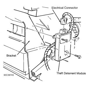
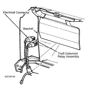
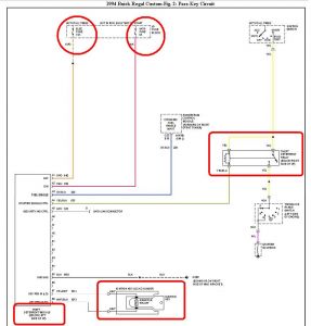
I don't believe the engine computer has anything to do with this. It has something to do with the Theft Deterrent Module. Here is the troubleshooting procedure for Pass-Key anti-theft system.
TROUBLE SHOOTING
1. Check ignition key assembly for a cracked, dirty, or coated resistor pellet. Ensure ignition key is free from excess plastic around resistor pellet contacts.
2. Using PASS-Key II(R) Interrogator (J 35628-A) check ignition key. If key code window shows an
"E", replace key.
3. Look into key opening and check key pellet sensing contacts in ignition lock cylinder. If contacts
are damaged or not Silver, replace lock cylinder.
4. Check for an open ECM IGN fuse No. 5 or ECM BATT fuse No. 4. In addition, check instrument
panel fuse block contacts for each fuse.
TESTING
SYSTEM TEST
Engine Does Not Crank, SECURITY Indicator Lights For About 5 Seconds (Bulb Check), Then Goes Out
1) If vehicle is equipped with automatic transmission, go to step 2). If vehicle is equipped with manual
transmission, check for battery voltage at clutch start switch when ignition switch is in START position.
Disconnect clutch start switch connector. Connect a test light between terminal "A" (Dark Green wire)
and ground. If test light lights when ignition switch is in START position, check starting system. If test
light does not light, go to next step.
2) Disconnect starter enable relay. Connect test light between relay connector terminal A2 (Yellow wire) and ground. Turn ignition switch to START position. If test light does not light, check for poor connection or open circuit at ignition switch.
3) If test light lights, connect a test light between starter enable relay connector terminal C2 (Yellow
wire) and ground. Turn ignition switch to START position. If test light does not light, check for an open
circuit in Yellow power feed wire.
4) If test light lights, connect fused jumper wire between starter enable relay connector terminals C1 and C2 (Yellow wire). Turn ignition switch to START position. If engine does not crank, diagnose starting and charging system.
5) If engine cranks disconnect fused jumper wire. Connect a test light between starter enable relay
connector terminals A1 (Yellow/Black wire) and voltage. Turn ignition switch to START position. If
test light does not light check Yellow/Black wire for short to voltage.
6) If starter does operate or test light lights, check for poor relay connection. If connection is okay,
replace relay.
Engine Cranks But Will Not Start, SECURITY Indicator Lights For Approximately 5 Seconds (Bulb Check), Then Goes Out
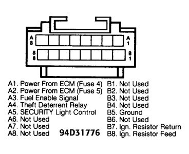
1) Disconnect theft deterrent module. Turn ignition switch to RUN position. Measure voltage between
decoder connector terminal A3 (Dark Blue wire) and ground.
2) If voltage is not about 5 volts, check Dark Blue wire between ECM and theft deterrent module for an open or short circuit. If Dark Blue wire is okay, perform normal engine performance diagnosis.
3) If voltage is about 5 volts go to next step.
4) Check Dark Blue wire for an open or short circuit between theft deterrent module connector terminal A3 and Powertrain Control Module (PCM). If wiring is okay, replace PCM.
SECURITY Indicator Lights Steadily (Not Flashing), Engine Starts
1) Disconnect theft deterrent module. Turn ignition switch to RUN position. If SECURITY indicator does not light, go to LOCK CYLINDER & HARNESS TEST. If keys, lock cylinder and lock cylinder harness are okay, replace theft deterrent module.
2) If SECURITY indicator lights, check for short circuit to ground between theft deterrent module connector terminal A5 (Gray wire) and instrument cluster connector DLC terminal "D". Check instrument cluster printed circuit for shorts and repair as necessary.
SECURITY Indicator Never Lights, Engine Starts
1. Disconnect theft deterrent module. Attach a 10-amp fused jumper between theft deterrent module connector terminal A5 (Gray wire) and ground. Turn ignition switch to RUN position.
2. If SECURITY indicator lights, check for poor connection at theft deterrent module. If connection
is okay, replace theft deterrent module.
3. If SECURITY indicator does not light, check for poor connection or open circuit in Gray wire
between theft deterrent module terminal A5 and instrument cluster connector DLC terminal "D".
Check for an open circuit in Pink wire between instrument cluster connector terminal D3 and
splice. Check instrument cluster printed circuit and indicator bulb and repair as necessary.
Lock Cylinder & Harness Test
1. Put ignition key into PASS-Key II(R) Interrogator (J 35628-A). Turn interrogator on. Read key
code shown on interrogator display.
2. If displayed key code is not a value of 1-15, clean and retest key. If key code is invalid, replace key. If displayed key code is a value of 1-15, record displayed key code. Turn interrogator off.
3. Connect interrogator to 2-pin ignition switch lock cylinder harness connector at base of steering
column. Put ignition key into ignition switch lock cylinder.
4. Turn interrogator on. While checking display on interrogator, turn ignition switch slowly to START position. If displayed key code value does not match value recorded in step 2), check for poor connection. If connection is okay, replace ignition switch lock cylinder and harness.
5. If displayed key code value matches value recorded in step 2), use a test light and front probe 2-pin connector at base of steering column between terminal "B" (Purple/White wire) and battery voltage. If test light does not light, go to step 7). If circuit is okay, replace theft deterrent module.
6. If test light lights, disconnect theft deterrent module. Turn ignition switch to RUN position. Use
test light and front probe 2-pin connector at base of steering column between terminals "A" and "B". If test light lights, repair short to voltage in White/Black wire. If test light does not light, check White/Black wire for an open or short circuit to ground. If wire is okay, replace theft deterrent module.
7. If test light did not light in step 5), disconnect theft deterrent module. Use a test light and probe
between theft deterrent module terminal B5 (Black wire) and battery voltage. If test light does not light, repair open circuit in Black/White or Black wire. If test light lights, check for poor or open circuit at module terminal B5 (Black/White or Black wire) or terminal B7 (Purple/White wire). If connections and wiring are okay, replace theft deterrent module.


Sunday, January 18th, 2009 AT 11:36 PM


