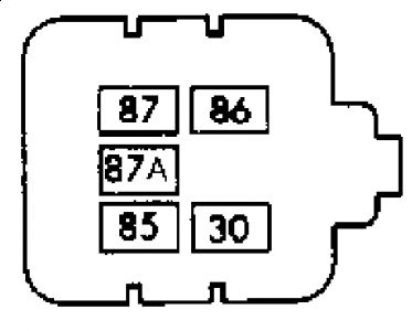
BLOWER RELAY TEST LeSabre & Park Avenue 1. Turn ignition switch to RUN position. Remove blower speed relay. Set A/C-heater mode selector switch to NORM position. Set blower switch to HIGH position. Measure voltage between blower speed relay connector terminal No. 86 (Black wire) and ground. See Fig. 14 . If battery voltage is present, go to next step. If battery voltage is not present, check Black wire for open or short to ground and check fuse 5D in instrument panel fuse block. 2. Measure voltage between blower speed relay connector terminals No. 30 (Purple wire) and ground. If battery voltage is present, go to next step. If battery voltage is not present, check Purple wire for an open. 3. Measure voltage between blower speed relay connector terminals No. 85 (Orange wire) and No. 86 (Black wire) of blower speed relay connector. If voltmeter reads battery voltage, go to next step. If volt-meter does not read battery voltage, check Orange and Black wires for an open or short to ground. Check A/C-heater control panel connector terminal "H" and in-line connector for proper terminal contact. If wiring and connections are good, perform A/C- HEATER CONTROL PANEL TEST. 4. Connect a fused jumper wire (25-amp fuse) between blower speed relay connector terminals No. 30 (Purple wire) and No. 87 (Red wire). If blower runs at high speed, perform BLOWER HIGH SPEED RELAY TEST. If blower does not run, check A/C-heater control panel wiring for opens or shorts.BLOWER HIGH SPEED RELAY TEST LeSabre & Park Avenue 1. Turn ignition switch to RUN position. Remove blower high speed relay. Set A/C-heater mode selector switch to HEATER position. Measure voltage between blower speed relay connector terminal No. 87A (Dark Blue wire) and ground. See Fig. 14 . If battery voltage is present, go to next step. If battery voltage is not present, check Dark Blue wire for open or short to ground. Check blower resistor terminal for proper contact. If wire and terminals are okay, perform BLOWER MOTOR RESISTOR TEST. 2. Connect a fused jumper wire between blower speed relay connector terminals No. 30 (Purple wire) and No. 87A (Dark Blue wire). If blower operates, replace high speed blower relay. If blower does not operate, turn ignition switch off, reinstall blower relay and go to next step. 3. Turn ignition switch to RUN position. Disconnect blower motor connector. Measure voltage between blower motor connector terminals. If battery voltage is present, check blower motor connector terminals for proper contact. If contact is good, replace blower motor. If battery voltage is not present, check for an open or short to ground in high speed blower relay wiring. 4. Turn ignition switch to RUN position. Remove blower high speed relay. Set A/C-heater mode selector switch to NORM position. Place blower switch in HIGH position. Measure voltage between blower speed relay connector terminal No. 86 (Black wire) and ground. See Fig. 14 . If battery voltage is present, go to next step. If battery voltage is not present, check Black wire for open. Check in-line connector for proper terminal contact. Check A/C-heater control panel connector terminal "B" for proper contact. If wiring and connections are okay, replace A/C- heater control panel. 5. Measure voltage between blower speed relay connector terminals No. 86 (Black wire) and No. 85 (Orange wire). If battery voltage is present, go to next step. If battery voltage is not present, check Black and Orange wires for an open. Repair as necessary. 6. Connect a fused jumper wire between blower speed relay connector terminals No. 30 (Purple wire) and No. 87 (Red wire). If blower operates, replace high speed blower relay. If blower does not operate, check underhood fuse block fuse No. 3. Check Red wire for an open or short to ground. If wiring and fuse is okay, replace high speed blower relay. BLOWER SWITCH TEST 1. Unplug blower motor resistor connector. Turn ignition switch to RUN position. Set A/C mode selector to VENT position. Set blower switch to medium low position. 2. Measure voltage between blower motor resistor connector Tan wire and ground. If battery voltage is present, go to next step. If voltage is not present, check Tan wire for open. If Tan wire is okay, replace blower switch. 3. Set blower switch to medium high position. Measure voltage between blower motor resistor connector Light Blue wire and ground. If voltage is present, go to next step. If voltage is not present, check Light Blue wire for open. If Light Blue wire is okay, replace blower switch. 4. Set blower switch to HIGH position. Measure voltage between blower high speed relay connector Orange wire and ground. If battery voltage is present, blower switch is okay. If battery voltage is not present, check Orange wire for an open. If Orange wire is okay, replace blower switch.BLOWER MOTOR RESISTOR TEST 1. Turn ignition off. Unplug blower motor resistor connector, located in rear center engine compartment. Using voltmeter, measure voltage at blower resistor connector terminal "D" (Light Blue wire) and ground. If battery voltage is present, go to next step. If battery voltage is not present, check for open in Light Blue wire. 2. Place blower switch in medium low position. Measure voltage at blower resistor connector terminal "C" (Tan wire). If battery voltage is present, go to next step. If battery voltage is not present, check for open in Tan wire. Check in-line connector for proper contact. Check A/C- heater control panel connector terminal "C" for proper contact. If wiring and contacts are good, replace A/C-heater control panel. 3. Place blower switch in medium high position. Measure voltage at blower resistor connector terminal "B" (Light Blue wire). If battery voltage is present, check blower resistor terminals for proper contact. If contact is okay, replace blower resistor. If battery voltage is not present, check for open in Light Blue wire. Check in-line connector for proper contact. Check A/C- heater control panel connector terminal "D" for proper contact. If wiring and contacts are good, replace A/C-heater control panel.
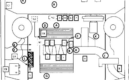
Relay is behind the engine, number N2, first one on the left.
Tuesday, July 21st, 2009 AT 3:44 PM


