Welcome to 2CarPros.
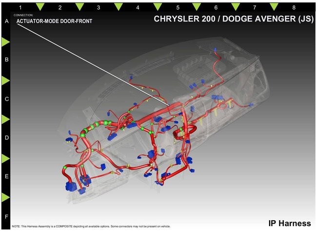
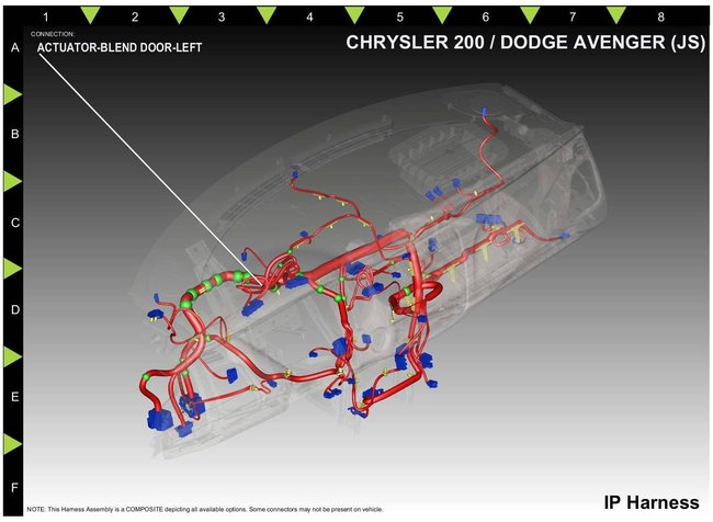
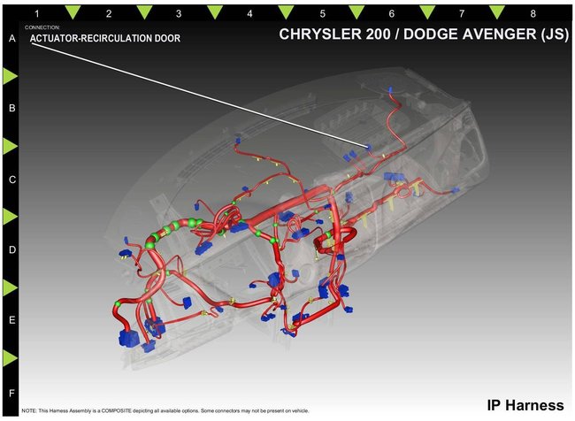
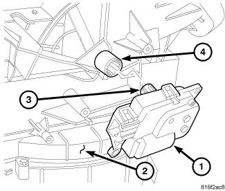
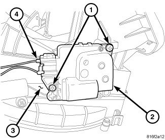
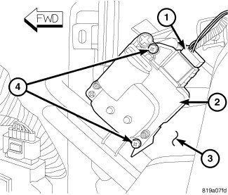
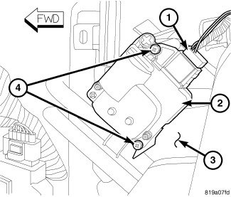
There is only one blend door actuator, but there are three total actuators. One is for temperature, one for mode (air flow), one for fresh air.
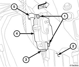
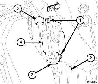
Picture 1 shows the mode door actuator.
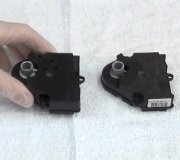
Picture 2 shows blend door actuator
Picture 3 shows recirculation / fresh air actuator
________________________________________
Here is a link that shows how in general to replace one:
https://www.2carpros.com/articles/replace-blend-door-motor
_______________________________________
I'm not sure exactly what is happening, but here are the directions for each.
______________________________________
RECIRCULATION DOOR ACTUATOR - REMOVAL
REMOVAL
WARNING:
Disable the airbag system before attempting any steering wheel, steering column or instrument panel component diagnosis or service. Disconnect and isolate the negative battery (ground) cable, then wait two minutes for the airbag system capacitor to discharge before performing further diagnosis or service. This is the only sure way to disable the airbag system. Failure to follow these instructions may result in accidental airbag deployment and possible serious or fatal injury.
NOTE:
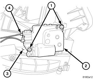
Illustration shown with instrument panel removed for clarity.
Picture 4
NOTE:
LHD model shown. RHD model similar.
1. Disconnect and isolate the negative battery cable.
2. Remove the glove box bin See: Glove Compartment > Removal and Replacement > Instrument Panel Glove Box - Removal.
3. Reach through the glove box opening in the instrument panel and remove the screws (1) that secure the recirculation door actuator (2) to the right side of the HVAC air inlet housing (3).
4. Disconnect the wire harness connector (4) from the recirculation door actuator and remove the actuator.
_________
INSTALLATION
NOTE:
Illustrations shown with instrument panel removed for clarity.
Picture 5
NOTE:
LHD model shown. RHD model similar.
1. Position the recirculation door actuator (1) to the right side of the HVAC air inlet housing (2).
2. Install the recirculation door actuator onto the air inlet housing. If necessary, rotate the actuator slightly to align the splines on the actuator output shaft (3) with those on the recirculation door pivot shaft adapter (4).
Picture 6
3. Install the screws (1) that secure the recirculation door actuator (2) to the air inlet housing (3). Tighten the screws to 2 Nm (17 in. lbs.).
4. Connect the instrument panel wire harness connector (4) to the recirculation door actuator.
5. Install the glove box bin See: Glove Compartment > Removal and Replacement > Instrument Panel Glove Box - Installation.
6. Reconnect the negative battery cable.
7. Initiate the Actuator Calibration function using a scan tool See: Heating and Air Conditioning > Initial Inspection and Diagnostic Overview > Heating-A/C System Diagnostics.
__________________________________
BLEND DOOR ACTUATOR - REMOVAL
REMOVAL
WARNING:
Disable the airbag system before attempting any steering wheel, steering column or instrument panel component diagnosis or service. Disconnect and isolate the negative battery (ground) cable, then wait two minutes for the airbag system capacitor to discharge before performing further diagnosis or service. This is the only sure way to disable the airbag system. Failure to follow these instructions may result in accidental airbag deployment and possible serious or fatal injury.
Picture 7
NOTE:
LHD model shown. RHD model similar.
1. Disconnect and isolate the negative battery cable.
2. On RHD models, remove the glove box bin See: Glove Compartment > Removal and Replacement > Instrument Panel Glove Box - Removal.
3. Disconnect the wire harness connector (1) from the blend door actuator (2) located on the left side of the HVAC air distribution housing (3).
4. Remove the two screws (4) that secure the blend door actuator to the air distribution housing and remove the actuator.
_________
BLEND DOOR ACTUATOR - INSTALLATION
INSTALLATION
Picture 8
NOTE:
LHD model shown. RHD model similar.
1. Position the blend door actuator (2) onto the left side of the HVAC air distribution housing (3). If necessary, rotate the actuator slightly to align the splines on the actuator output shaft with those in the blend air door linkage.
2. Install the two screws (4) that secure the blend door actuator to the air distribution housing. Tighten the screws to 2 Nm (17 in. lbs.).
3. Connect the wire harness connector (1) to the blend door actuator.
4. On RHD models, install the glove box bin See: Glove Compartment > Removal and Replacement > Instrument Panel Glove Box - Installation.
5. Reconnect the negative battery cable.
6. Initiate the Actuator Calibration function using a scan tool See: Heating and Air Conditioning > Initial Inspection and Diagnostic Overview > Heating-A/C System Diagnostics.
_____________________________
Mode door Actuator
REMOVAL
WARNING:
Disable the airbag system before attempting any steering wheel, steering column or instrument panel component diagnosis or service. Disconnect and isolate the negative battery (ground) cable, then wait two minutes for the airbag system capacitor to discharge before performing further diagnosis or service. This is the only sure way to disable the airbag system. Failure to follow these instructions may result in accidental airbag deployment and possible serious or fatal injury.
Picture 9
NOTE:
LHD model shown. RHD model similar.
1. Disconnect and isolate the negative battery cable.
2. Remove the glove box bin See: Glove Compartment > Removal and Replacement > Instrument Panel Glove Box - Removal.
3. Remove the screws (1) that secure the mode door actuator (4) to the bracket (5) located on the right side of the HVAC air distribution housing (2).
4. Disconnect the wire harness connector (3) from the mode door actuator and remove the actuator.
________
INSTALLATION
Picture 10
1. Position the mode door actuator (4) onto the bracket (5) located on the right side of the HVAC air distribution housing (2). If necessary, rotate the actuator slightly to align the splines on the actuator output shaft with those in the mode air door linkage.
2. Install the screws (1) that secure the mode door actuator to the air distribution housing. Tighten the screws to 2 Nm (17 in. lbs.).
3. Connect the wire harness connector (3) to the mode door actuator.
4. Install the glove box bin See: Glove Compartment > Removal and Replacement > Instrument Panel Glove Box - Installation.
5. Reconnect the negative battery cable.
6. Initiate the Actuator Calibration function using a scan tool See: Heating and Air Conditioning > Initial Inspection and Diagnostic Overview > Heating-A/C System Diagnostics.
_________________________________________
Let me know if this helps or if you have other questions.
Take care,
Joe
Images (Click to make bigger)
SPONSORED LINKS
Tuesday, May 7th, 2019 AT 6:32 PM
