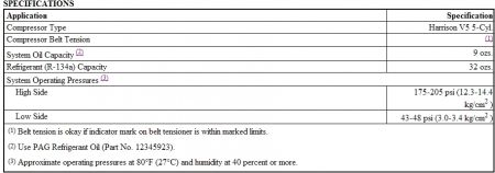
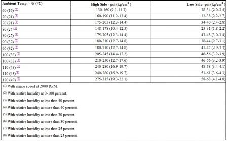
Okay, both readings are too warm for your current temperature and humidity, also the clutch should be cycling at these temperatures, the hotter it gets outside the less cycling it should do. The other thing to quickly look at is the floor wet on the passenger side?
By the book driver's side too warm:
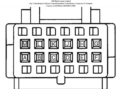
DRIVER'S-SIDE TEMPERATURE CONTROL SELECTOR INOPERATIVE 2000 Models (Single & Dual Zone Systems) 1. Check HVAC (10-amp) fuse in instrument panel fuse block. If fuse is okay, go to step 3. If fuse is blown, go to next step. 2. Check for short to ground in Brown wire between instrument panel fuse block and A/C-heater control panel Black 12-pin harness connector C2 terminal "C". See Fig. 3 . Repair Brown wire as necessary. After repair, go to step 18. 3. Turn ignition switch to OFF position. Disconnect A/C-heater control panel Black 12-pin harness connector C2. Using a DVOM, measure voltage between A/C-heater control panel harness connector C2 terminals "C" (Brown wire) and "K" (Black wire). If battery voltage does not exist, go to next step. If battery voltage exists, go to step 7. 4. Using a DVOM connected to ground, probe A/C-heater control panel harness connector C2 terminal "C" (Brown wire). If battery voltage does not exist, go to next step. If battery voltage exists, go to step 6. 5. Locate and repair poor connection or open in Brown wire between A/C-heater control panel Black 12-pin harness connector C2 terminal "C" and instrument panel fuse block. After repair, go to step 18. 6. Locate and repair poor connection or open in Black wire between A/C-heater control panel Black 12-pin harness connector C2 terminal "K" and ground. See WIRING DIAGRAMS . After repair, go to step 18. 7. Turn ignition switch to OFF position. Reconnect A/C-heater control panel harness connector C2. Disconnect left electric actuator. Turn ignition switch to ON position. Connect DVOM between left actuator harness connector terminal No. 7 (Black wire) and terminal No. 10 (Brown wire). If battery voltage does not exist, go to next step. If battery voltage exists, go to step 11. 8. Using a DVOM connected to ground, probe left actuator harness connector terminal No. 10 (Brown wire). If battery voltage does not exist, go to next step. If battery voltage exists, go to step 10. 9. Repair poor connection or open in Brown wire between left electric actuator harness connector terminal No. 10 and instrument panel fuse block. See WIRING DIAGRAMS . After repair, go to step 18. 10. Check for poor connection or open in Black wire between left electric actuator harness connector terminal No. 7 and ground connector located behind right side of instrument panel. After repair, go to step 18. 11. Using DVOM connected to ground, probe left electric actuator harness connector terminal No. 8 (Dark Blue wire). Move temperature control lever from COLD to HOT, and from HOT to COLD positions. If indicated voltage varies 1-12 volts, go to next step. If indicated voltage does not vary 1-12 volts, go to step 13. 12. Replace left electric actuator. After repair, go to step 18. 13. Check for short to ground in Dark Blue wire between A/C-heater control panel harness connector C2 terminal "G" and left electric actuator harness connector terminal No. 8. If a short to ground is present, go to next step. If a short to ground is not present, go to step 15. 14. Repair short to ground in Dark Blue wire between A/C-heater control panel harness connector C2 terminal "G" and left electric actuator harness connector terminal No. 8. 15. Check for poor connection or open in Dark Blue wire between A/C-heater control panel harness connector C2 terminal "G" and left electric actuator harness connector terminal No. 8. If problem is found, go to next step. If no problem is found, go to step 17. 16. Repair Dark Blue wire between A/C-heater control panel harness connector C2 terminal "G" and left electric actuator harness connector terminal No. 8 as necessary. After repair, go to step 18. 17. Replace A/C-heater control panel. See A/C-HEATER CONTROL PANEL under REMOVAL & INSTALLATION. After repair, go to next step. 18. Operate system to verify repair. If driver's side temperature control operates normally, repair is complete. If driver's side temperature control does not operate normally, return to step 1.


Low side at 50% humidity is a bit low, Raise idle to 2000 with gauges attached, low side will drop, when it gets to 23 the compressor should cycle off. Your orifice tube may be over 90% clogged, they can work up to that point.
Monday, March 22nd, 2021 AT 2:29 PM
(Merged)


