Dandy. If you're looking at the head lights fluctuating, the solution is to go back to the original system with the voltage regulator in the Engine Computer. That circuit causes very little trouble, so start by putting the wiring back to original, then, if there is a problem, we can diagnose that first. If the computer needs to be replaced, there's going to be a whole bunch of them in salvage yards now, and they should be rather inexpensive.
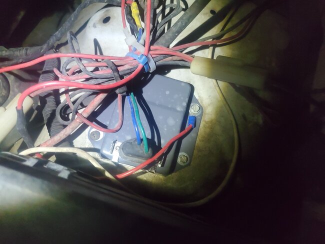
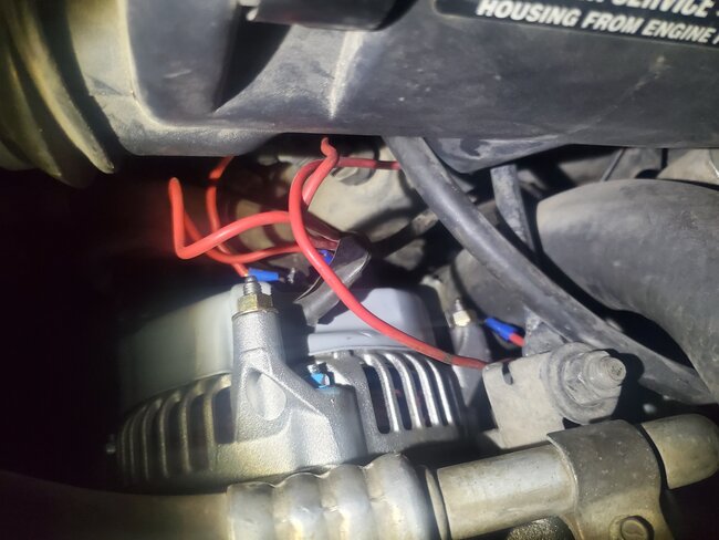
The blue wire on the regulator is the 12-volt feed to run its circuitry and it is where system voltage is monitored. That same wire feeds one of the two field terminals on the back of the alternator. Once current flows through the rotating field winding, it comes out the second terminal, then goes to the green wire at the regulator, then to ground through the housing. The regulator circuitry is a variable resistance to adjust the amount of current flow through the field winding. Field current is only three amps at maximum, but most of the time it will be around one amp or less. The amount of current determines the strength of its magnetic field.
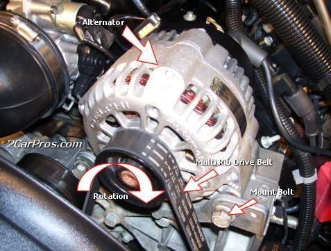
Three things are needed to generate a voltage mechanically. They are a wire, a magnetic field, and most importantly, movement between them. That's why we spin the field winding with a belt and pulley. Instead of a piece of wire, it's more efficient to make it into a coil. About a dozen of those are placed around the outside of the alternator. For the magnetic field, we use the rotating field winding / coil / rotor because it's easy to adjust its strength. It's not practical to adjust alternator output by increasing or decreasing engine speed.
Along with the huge list of innovations Chrysler developed, (by the way, they copyrighted the term, "alternator"), they were the first with the electronic voltage regulator, identical to what you're using. It has temperature compensation built in. Charging a battery is a chemical reaction. Those slow down as temperature goes down. In response, this regulator will bump up charging voltage a little in colder weather to help get the battery to charge. Beyond that, there is one set value this regulator is shooting for. The only information it has to go on is system voltage on the blue wire.
By building the voltage regulator into the Engine Computer, that circuitry has access to all the information the computer does, so it can adjust system voltage based on more things. For example, it knows when you're at wide-open-throttle and you need every horsepower you can get. The computer can stop field current flow for those few seconds to stop the alternator from being a load on the engine. That can save up to five horsepower. If the engine is running too hot, the computer may cut back alternator output to put less drag on the engine. It can also anticipate loads about to be switched on, like the AC compressor clutch. It will raise idle speed just ahead of that to prevent a stumble, and it can increase alternator output to meet the needs of that clutch circuit. Basically, the computer can command adjustments in charging system output based on any number of things the computer knows and reacts to.
The problem with this circuit modification is all those variables have been eliminated because nothing is built into the external regulator. The pulsing head lights are likely the result of "hunting" system voltage on the regulator's blue wire. Something else is causing a pulsing current draw, and the regulator is either not reacting to it or it's overreacting to it. Normally this is solved by the voltage regulator monitoring system voltage at some other place. The best example is when a vehicle has a digital dash. Those will flicker in brightness with the slightest variation in the voltage supply that runs them. For that reason, they use that voltage supply wire to monitor system voltage so it is held perfectly steady. That leaves the rest of the vehicle's circuitry susceptible to minor voltage fluctuations. Often that shows up as a barely perceptible flickering of the head lights. That is less irritating than a flickering instrument cluster.
If you want to stick with the current setup, the first place to look is where the regulator is grounded to the body sheet metal. Place one voltmeter probe on the battery's negative post and the other probe on the regulator's metal housing. Switch the voltmeter to one of its lowest ranges. The perfect voltage reading is 0.00 volts. You can expect to find a few hundredths of a volt, but more than a couple of tenths indicates lack of proper ground. The mounting surface must be paint-free and rust-free, and the bolts must be tight. Also look at the smaller of the two wires leaving the negative battery cable clamp. Where it bolts to the body must also be free of paint and rust. If you find excessive voltage in this test, there are additional tests to narrow down the cause.
This ground path is the ground that the system voltage is in reference to, and it is the ground path for field current through the alternator's field winding. That's like having groups of people exiting two buildings, side by side. The flow out of each door is smooth and free, but congestion occurs on the sidewalk when both groups get mixed together. That congestion slows down both groups of people. The two currents from the two different circuits interact the same way in the regulator's ground path. That's why every wire and every connection must be in good condition. When there's any resistance, current flow through it causes a small "voltage drop". That voltage affects the other circuit(s) that share that ground. In my people story, a poor ground is like having a very skinny sidewalk for the people to flow through. They interact a lot and slow down both groups. Good grounds is like having a really wide sidewalk so the groups of people don't interact very much.
While it won't help with the diagnosis, if you want to see these voltage fluctuations with a voltmeter, you'll need the older "analog" style with a pointer. It's easy to see the pointer moving around. Digital meters work by taking a reading, analyzing it, then displaying it while it takes the next reading. That makes those readings bounce around too quickly to read. Digital meters are better for use on the higher ranges where little fluctuations don't show up in the readings.
SPONSORED LINKS
Monday, December 30th, 2024 AT 1:28 PM


