Yes, I never believed in replacing parts without testing and confirming that they are faulty.
Here are the diagnostic procedures.
BLOWER MOTOR DOES NOT RUN
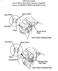
1 . Check fuses No. 37 (40 -amp) and No. 19 (7.5 - amp). If fuses are okay, unplug connectors from blower relay and blower high relay. See Fig. 12 .

2 . Turn ignition on. Check for voltage between Black/Yellow wire in blower relay connector and chassis ground. If battery voltage exists, go to next step. If battery voltage does not exist, repair open circuit in Black/Yellow wire between fuse No. 19 and blower relay.
3 . Check for voltage between Black/Yellow wire in blower high relay connector and ground. If battery voltage exists, go to next step. If battery voltage does not exist, repair open circuit in Black/Yellow wire between fuse No. 19 and blower high relay.
4 . Turn ignition off. Check for continuity between Black wire in blower high relay connector and ground. If continuity exists, go to next step. If continuity does not exist, repair open circuit in Black wire between blower high relay and ground.
5 . Check for continuity between Black wire in blower relay connector and ground. If continuity exists, go to next step. If continuity does not exist, repair open circuit in Black wire between blower relay and ground.
6 . Check for voltage between Blue/White wire in blower relay connector and ground. If battery voltage exists, go to next step. If battery voltage does not exist, repair open circuit in Blue/White wire between blower relay and fuse No. 37.
7 . Unplug blower motor 2 -pin connector, located near blower relays. Check for continuity in Blue/Red wire between blower relay connector and blower 2 -pin connector. If continuity exists, go to next step. If continuity does not exist, repair open circuit in Blue/Red wire between blower relay and blower motor.
8 . Connect battery voltage to Blue wire in blower motor connector. Connect Black wire in blower motor connector to ground. If blower motor runs, go to next step. If blower motor does not run, replace motor.
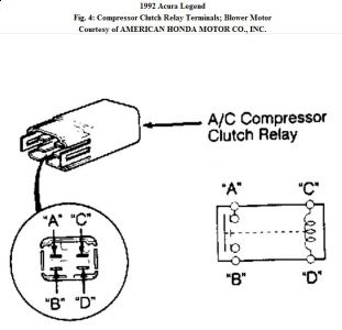
9 . Connect ohmmeter leads to terminals "C" and "D" of blower motor relay. See Fig. 4 . If continuity does not exist, replace relay. If continuity exists, go to next step.

10 . Connect ohmmeter to terminals "A" and "B" of relay. Connect terminal "C" to battery
voltage. Connect terminal "D" to ground. Relay should click and ohmmeter should indicate
continuity. If relay functions as specified, go to next step. If relay does not function as
specified, replace relay.
11 . Check Blue/Black wire for continuity between blower high relay and blower motor. If continuity exists, go to next step. If continuity does not exist, repair open circuit in Blue/Black wire.
12 . Connect ohmmeter leads to terminals "C" and "D" of blower high relay. See Fig. 4 . If continuity does not exist, replace relay. If continuity exists, go to next step.
13 . Connect ohmmeter to terminals "A" and "B" of relay. Connect terminal "C" to battery voltage. Connect terminal "D" to ground. Relay should click and ohmmeter should indicate continuity. If relay functions as specified, go to next step. If relay does not function as specified, replace relay.
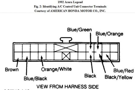
14 . Reconnect wiring to blower relay, blower high relay and blower motor. Remove A/C control unit. Turn ignition on. Using a jumper wire, connect Orange/White wire in A/C control unit 22 -pin connector to chassis ground. See Fig. 2 .

15 . If blower motor does not run, repair open circuit in Orange/White wire between control unit and blower high relay. If blower motor runs, install a known good control unit.
Friday, November 27th, 2009 AT 12:24 PM


