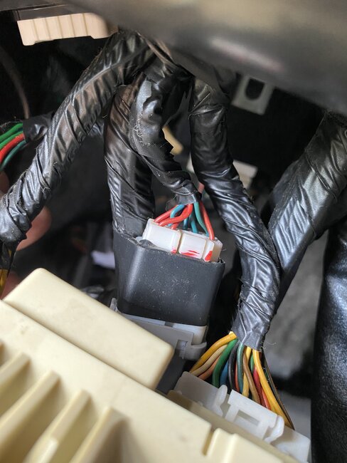
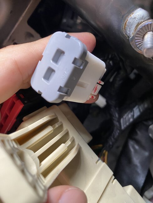
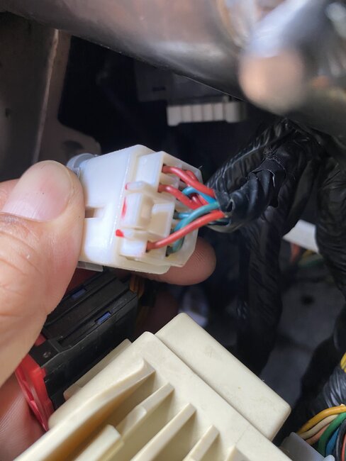
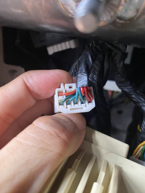
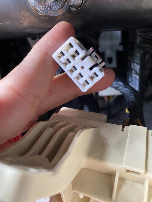
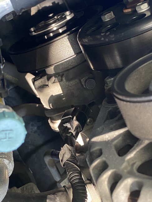
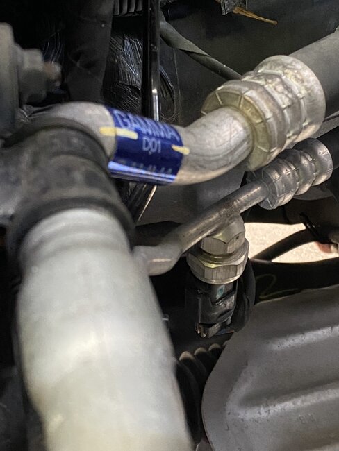
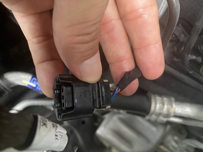
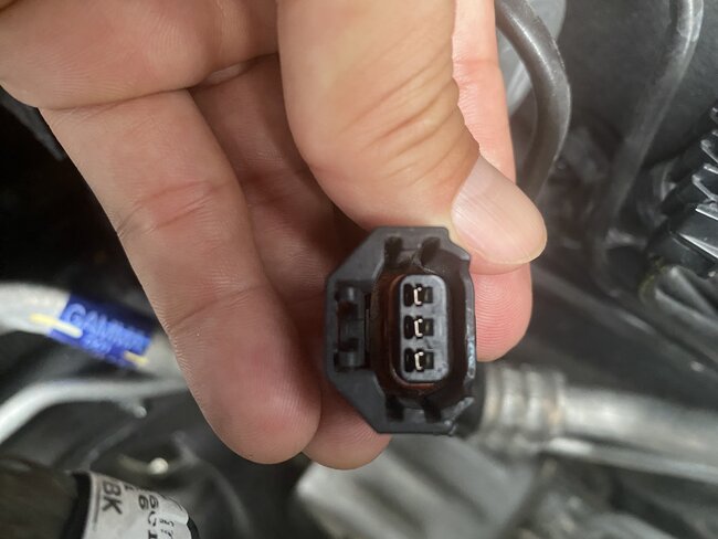
That connector with the red and blue wires to it are the canbus high and low communications wires, as long as the connector cover and pins to it are tight, that's good, with it plugged back in do you still have no communication with HVAC module?
If not, then we will check powers and grounds at the back of the module. If you have voltage on the feed pin at the back of the AC compressor connector, that's fine,
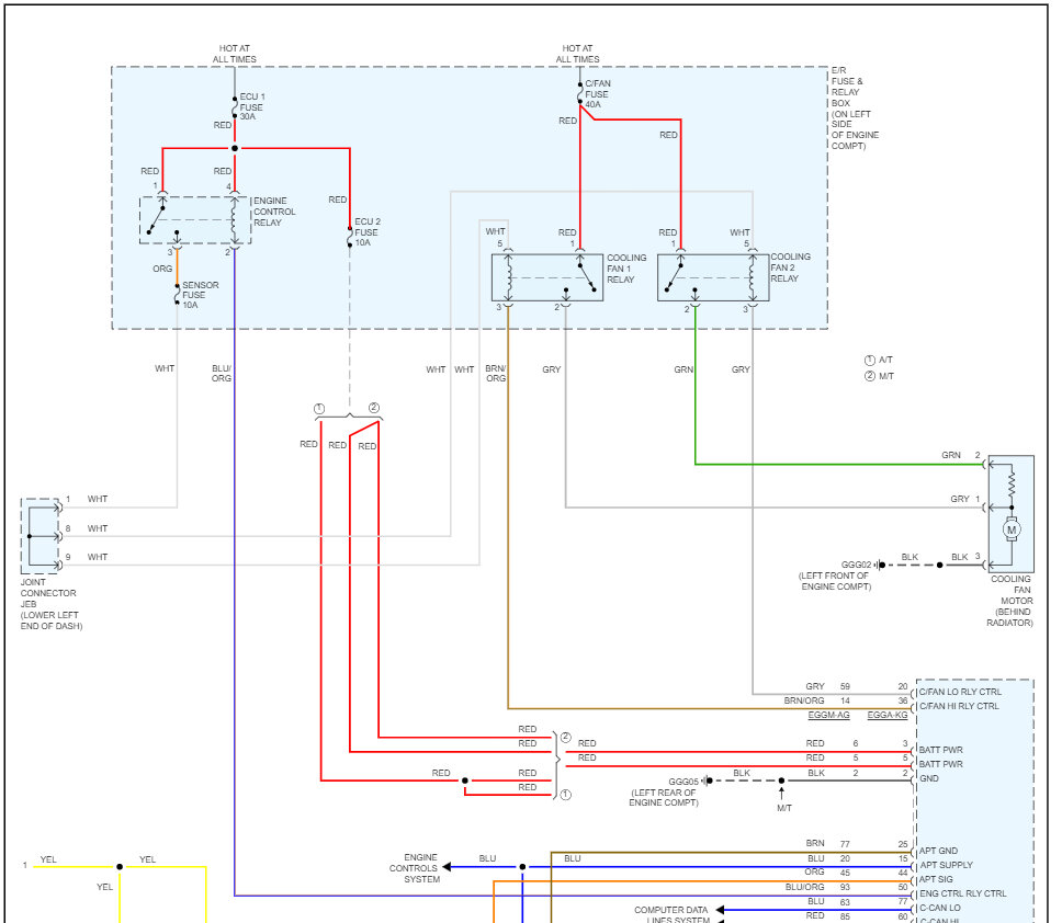
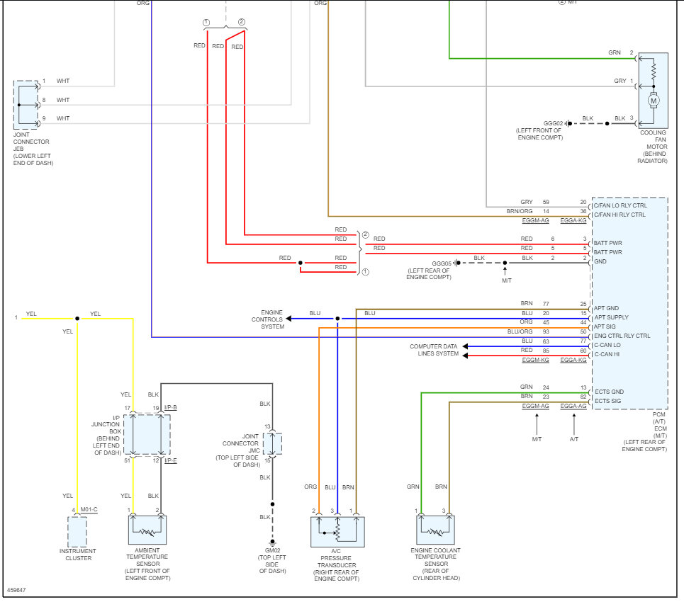
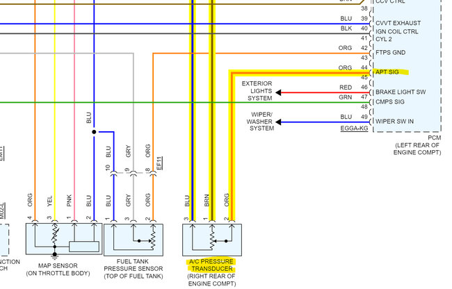
Looking through other "Verified Repairs" another Technician ran into this same exact issue with a Manual AC system. He had no communication with the HVAC control module, replaced it and still had no comms, it was verified the correct amount of Freon was in the system, his repair was finally replacing the compressor and that took care of the issue. The ecm seems to be responsible for the AC Pressure transducer and control of the compressor, even though the wiring diagrams show things differently.
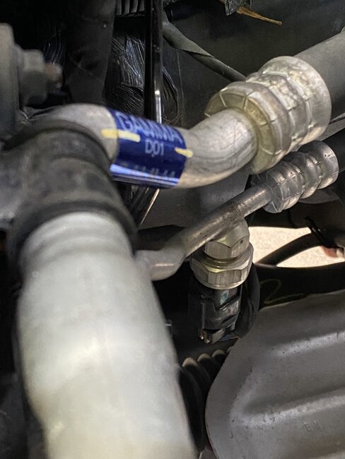
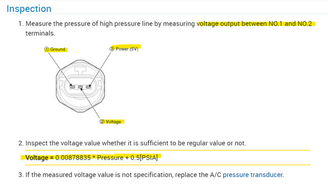
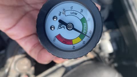
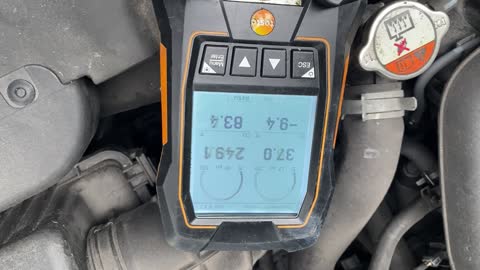
This is the procedure for testing the 3 wire AC pressure transducer. You will have to do the voltage calculation highlighted; I believe you had 158psi correct? So (voltage= 0.00878835 x pressure (158) + 0.5= 1.88volts roughly on pin #2(signal pin) and pin# 1 Ground). If you have a voltage signal that correlates to the high pressure reading, then the AC pressure transducer is ok.
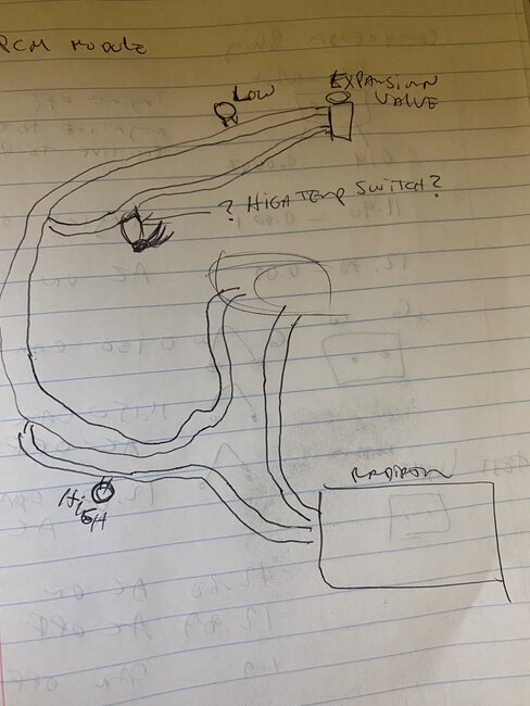
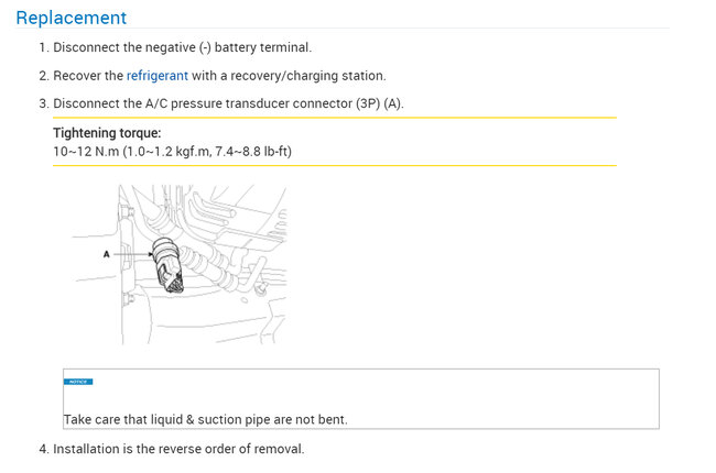
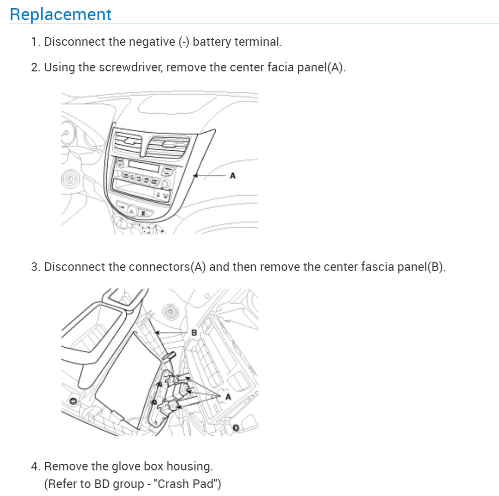
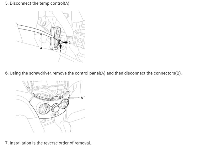
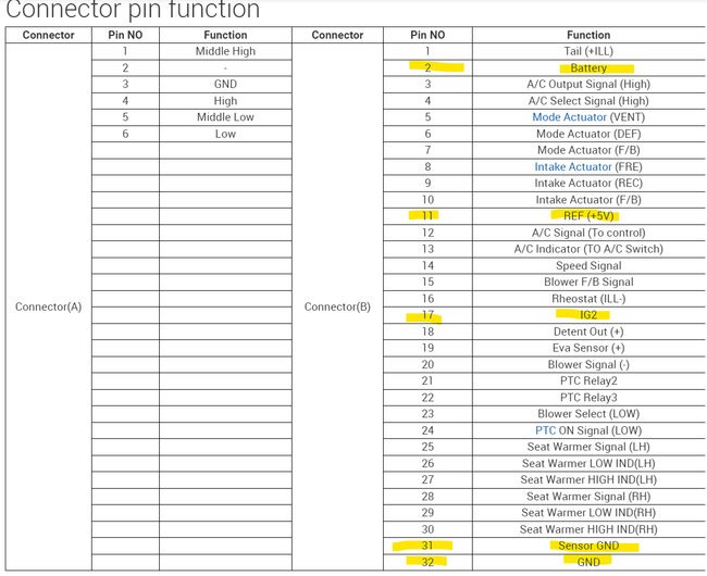
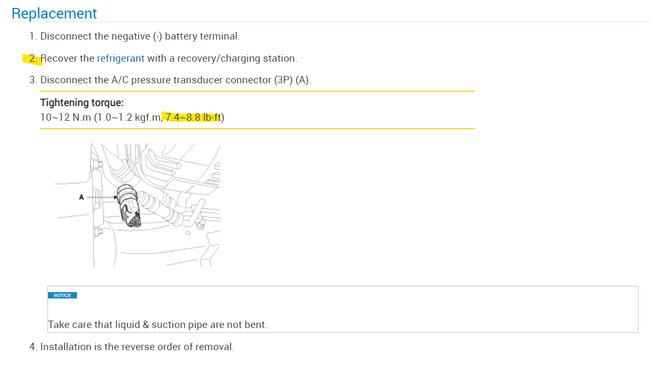
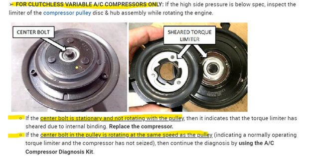
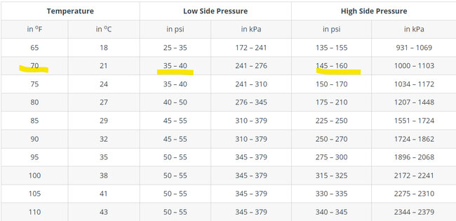
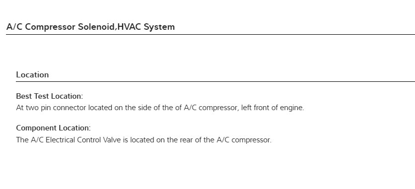
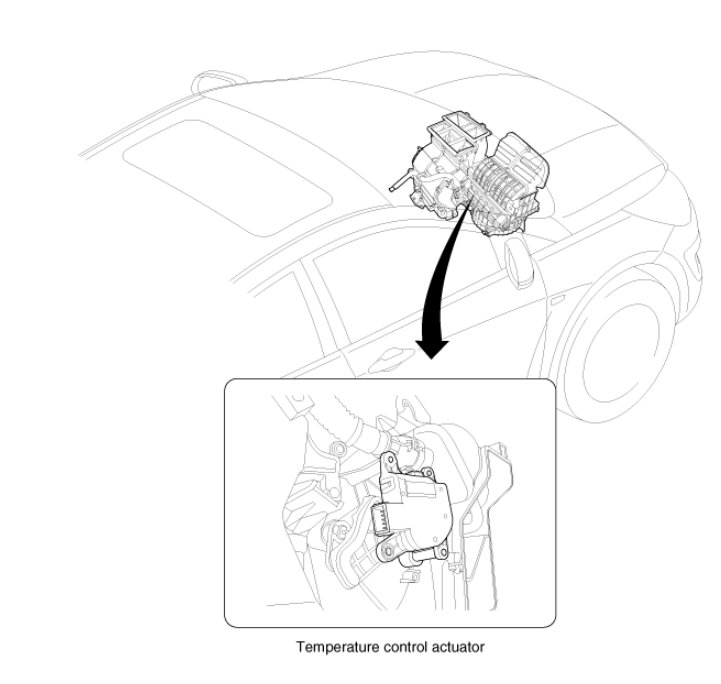
If the pressure is incorrect or the temperature is too high the ECM will shut down the compressor. So, you can do a couple things here. You can take it somewhere and have them evacuate the Freon and measure how much is in there and see if it's correct. (Which I recommend before replacing the compressor). There is also a Technical Service Bulletin on this compressor operation, but it looks to be more for a shop or dealership testing setup, some of these compressors have an external control valve (ECV). Under this TSB though, they are able to get pressure readings with the GDS which is going to be their factory scan tool. You can try looking under the Body Control Module and see if there are any data PIDs for AC pressure under that module. But yours is a clutch-less variable compressor. The TSB requires a special test kit made by Bosch. It might be that the factory scan tool is needed to access the control module, some of the newer systems, manufacturers are limiting access with aftermarket scan tools, I have heard this is becoming an issue, I'm going to post to other technicians and see if the manual A/C system doesn't use communications with scan tools for whatever reasons. In the meantime, diagrams 4 and 5 show how to access the back of the AC Control head unit. We can verify there is power and ground for it and see if there are any canbus (Blue and Red) wires on pins 27 and 28. You should be able to get an average voltage reading if there is network activity on those wires.
There should be an AC Request data PID in the PCM data
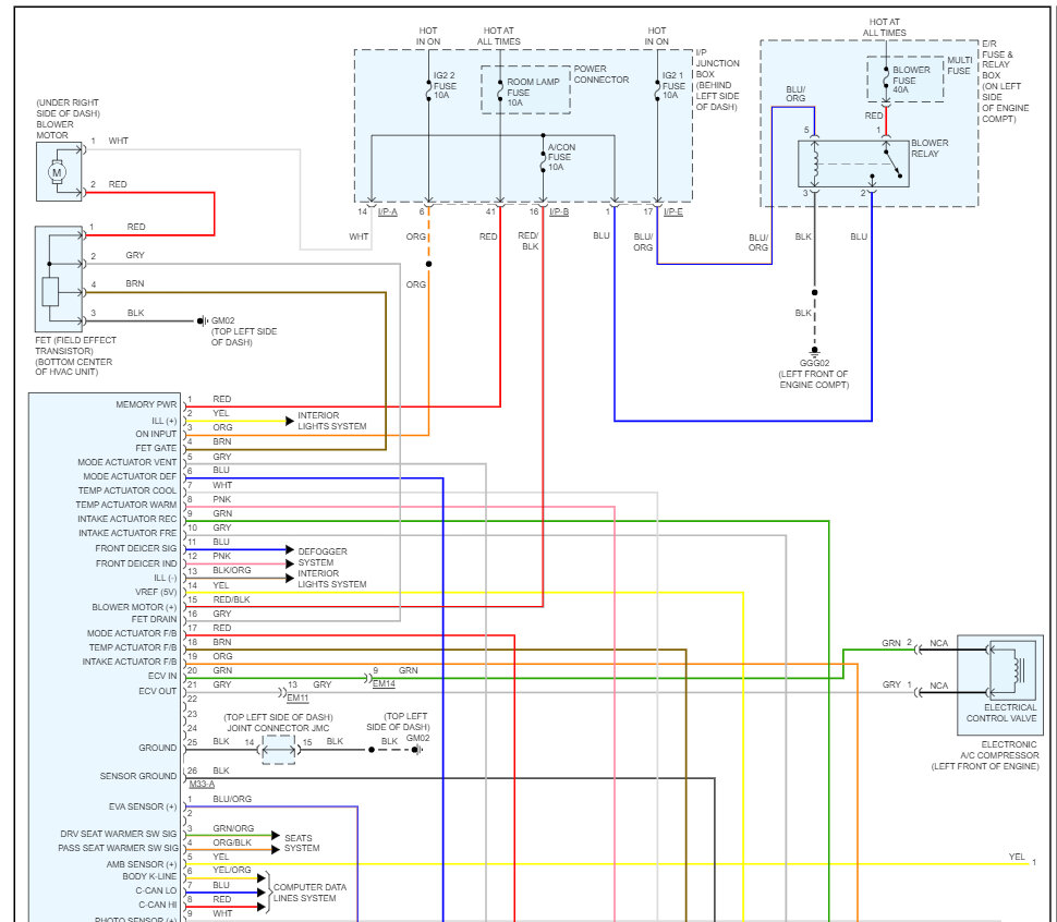
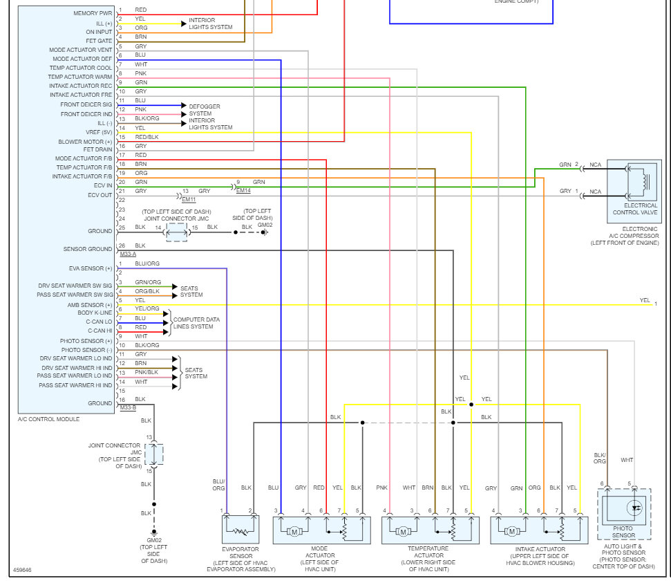
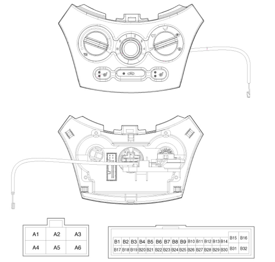
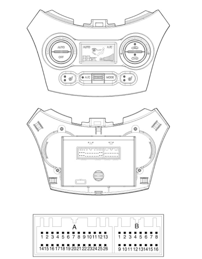
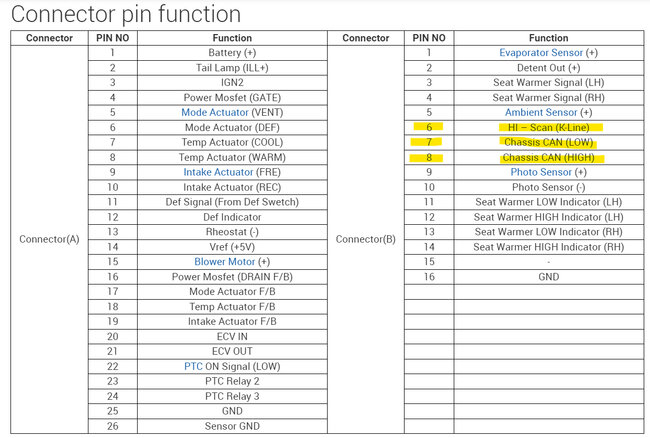
Ok I found the problem; the wiring diagrams are incorrect. The Manual AC controller does not have canbus or K line communications at all. Only the Auto A/C Controller does, that's why it's not coming up on your scan tool. Diagrams 6, 7 are the Manual Control Head and the connector pinout, diagrams 8, 9 are the Auto AC Controller, you'll notice in the pinout (Connector B, pins 6-K line, 7 CANbus Low, 8 CANbus High, ) those are the communications pins, the K line is for scan tool communications, I don't know why the correct module and connector diagrams were so difficult to find and why they are so incorrect. But this explains the scan tool issues.
Diagram 10 was the suggested testing process from another tech that knows this system well.
Images (Click to make bigger)
Friday, May 19th, 2023 AT 12:42 PM
