Hi,
Here are the directions for removal and replacement of the module. The attached pics correlate with the directions.
____________________________________________________________
1993 Chevrolet Cavalier/Z24 L4-134 2.2L
Master Cylinder and Hydraulic Modulator Assembly (with ABS)
Vehicle Brakes and Traction Control Hydraulic System Brake Master Cylinder Service and Repair Procedures Master Cylinder and Hydraulic Modulator Assembly (with ABS)
MASTER CYLINDER AND HYDRAULIC MODULATOR ASSEMBLY (WITH ABS)
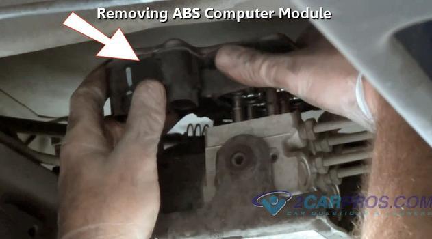
ABS Hydraulic Modulator Assembly Removal
Pic 1
Brake Pipe Connections
pic 2
WARNING: To avoid personal injury, due to a retained load on the modulator assembly, the "Gear Tension Relief" function of the TECH 1 scan tool must be performed prior to removal of the brake control and motor assembly.
Remove or Disconnect
1. Using Tech 1, performing "Gear Tension Relief Sequence".
2. Two solenoid electrical connectors.
3. Fluid level sensor electrical connector.
4. 6-Pin and 3-Pin motor pack electrical connectors.
5. Move air cleaner cover and/or intake duct assembly aside.
6. Four brake pipes.
Place shop cloth on top of motor pack to catch any dripping fluid. Take care not to allow brake fluid to enter the bottom of the motor pack or the electrical connectors. Plug open lines to prevent fluid loss and contamination.
7. Two nuts attaching hydraulic modulator/master cylinder assembly to vacuum booster.
It may be necessary to remove vacuum check valve from vacuum booster to gain access to the nut closest to the check valve.
8. Hydraulic modulator/master cylinder assembly From vehicle.
Install or Connect
Hydraulic modulator/master cylinder assembly in vehicle.
It may be necessary to remove vacuum check valve From vacuum booster to gain access to the nut closest to the check valve.
2. Two nuts attaching hydraulic modulator/master cylinder assembly to vacuum booster.
Tighten
Nuts to 27 Nm (20 lb. Ft.).
3. Four brake pipes to hydraulic modulator/master cylinder assembly.
Tighten
Tube nuts to 24 Nm (18 lb. Ft.).
4. Motor pack 6-Pin and 3-Pin electrical connectors.
5. Fluid level sensor electrical connector.
6. Two solenoid electrical connectors.
Bleed system, refer to Brake Bleeding / Service and Repair.
__________________________________________________
Here are the directions for manual bleeding of the abs module.
_________________________________________________
1993 Chevrolet Cavalier/Z24 L4-134 2.2L
Manual Bleeding
Vehicle Brakes and Traction Control Hydraulic System Brake Bleeding Service and Repair Procedures Hydraulic System Bleeding ABS System Bleed Procedures Manual Bleeding
MANUAL BLEEDING
Manual Bleeding
Note: Use only DOT 3 brake fluid from a clean, sealed container. Do not use fluid from an open container that may be contaminated with water. Do not use DOT 5 brake fluid.
Note: In the following steps, use a suitable container and/or shop cloths to catch fluid and prevent it from contacting any painted surfaces. Clean fluid reservoir cover and surrounding area.
1. Remove fluid reservoir cover.
2. Inspect fluid level in reservoir and add to the correct level if necessary.
3. Install fluid reservoir cover.
Hydraulic Modulator/Master Cylinder Assembly
Attaching Bleeder Tube
pic 3
1. Prime hydraulic modulator/master cylinder assembly.
2. Attach bleeder hose to rearward bleeder valve and submerge opposite hose end in clean container partially filled with brake fluid.
3. Slowly open rearward bleeder valve 1/2 to 3/4 turns.
4. Depress brake pedal and hold until fluid begins to flow.
5. Close valve and release brake pedal. Repeat procedure until no air bubbles are present.
6. Repeat procedure for forward bleeder valve until fluids begins to flow.
Note: Once fluid is seen to flow from both modulator bleeder valves, the hydraulic modulator/master cylinder assembly is sufficiently full of fluid. However, it may not be completely purged of air. At this point move to the wheel brakes and bleed them. This ensures that the lowest points in the system are completely free of air and then the hydraulic modulator/master cylinder assembly can be purged of any remaining air.
1. Remove fluid reservoir cover.
2. Inspect fluid level in reservoir and add to the correct level if necessary.
3. Install fluid reservoir cover.
4. Raise vehicle and suitably support.
Bleed sequence: Right rear. Left rear. Right front. Left front.
5. Bleed wheel brakes in sequence shown above. Attach bleeder hose to bleeder valve and submerge opposite hose in clean container partially filled with brake fluid. Open bleeder valve. Slowly depress brake pedal. Close valve and slowly release brake pedal. Wait 5 seconds.
6. Repeat Step 5, including the five seconds wait until brake pedal feels firm at half travel and no air bubbles are observed in the bleeder hose.
7. Repeat Steps 5 and 6 on left rear wheel brake.
8. Repeat Steps 5 and 6 on front wheel brakes.
Note: To assist in freeing entrapped air, tap lightly on caliper casting with a rubber mallet
9. Lower vehicle.
10. Remove fluid reservoir cover.
11. Inspect fluid level in reservoir and fill to the correct level if necessary.
12. Install fluid reservoir cover.
13. Bleed the ABS hydraulic modulator/master cylinder assembly.
14. Attach bleeder hose to rearward bleeder valve and submerge opposite end in clean container partially filled with brake fluid.
15. Depress brake pedal with moderate force. Slowly open rearward bleeder valve 1/2 to 3/4 turns and allow fluid to flow.
16. Close valve and release brake pedal. Wait five seconds.
17. Repeat above steps, including the five second wait, until all the air is purged from the system.
18. Repeat procedure for forward bleeder valve until all air is purged from the system.
19. Remove fluid reservoir cover.
20. Inspect fluid level in reservoir and fill to the correct level if necessary.
21. Install fluid reservoir cover.
22. With ignition "on" apply brake pedal with moderate force and hold. Note pedal travel and feel. If pedal feels firm and constant and pedal travel is not excessive, start the engine. With the engine running, recheck the pedal travel. If it's still firm and constant and pedal travel is not excessive, go to Step 23. If pedal feels soft or has excessive travel either initially or after engine start, use the Tech 1, "Release" then "Apply" the motors 2 to 3 times and cycle the solenoids 5 to 10 times. Be sure to "Apply" the front and rear motors to ensure the pistons are in the upmost position. Now repeat the procedure and start at Step 1.
23. Road test the vehicle. Make several normal (non-ABS) stops from a moderate speed to ensure proper brake system function.
______________________________
Let me know if this helps or if you have other questions.
Take care,
Joe
Images (Click to make bigger)
Thursday, February 25th, 2021 AT 9:37 AM
(Merged)


