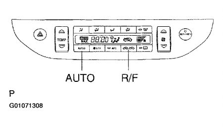
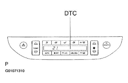
DTC 21: SOLAR SENSOR CIRCUIT
Circuit Description
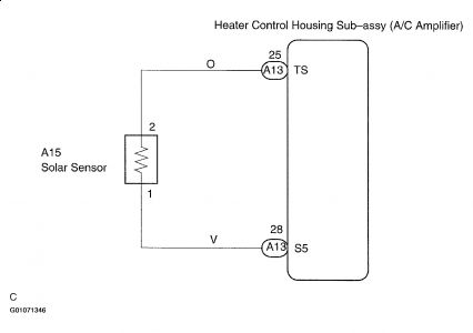
A photo diode in the solar sensor detects solar radiation and sends signals to the A/C amplifier.
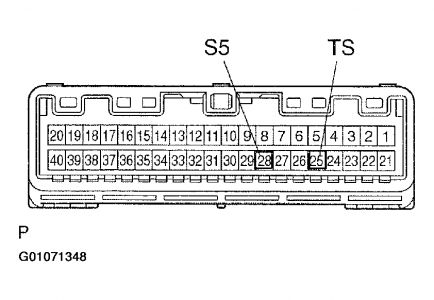
Remove A/C amplifier with connectors still connected.
Turn ignition switch ON.
Measure voltage between terminals S5 and TS of A/C amplifier connector when the solar sensor is subject to an electric light, and when the sensor is covered by a cloth
Voltage:
Sensor subject to electric light: 0.8 - 3.3 V
Sensor is covered by a cloth: Below 0.8 V
HINT:
As the inspection light is moved away from the sensor, the voltage increases.
A: GO TO NEXT STEP.
B: PROCEED TO NEXT CIRCUIT INSPECTION SHOWN ON PROBLEM SYMPTOM TABLE
C: CHECK AND REPLACE HEATER CONTROL HOUSING SUB-ASSEMBLY
INSPECT COOLER (SOLAR SENSOR) THERMISTOR
Remove cooler (solar sensor) thermistor.
Cover sensor with a cloth.
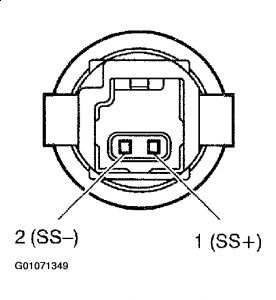
Measure resistance between terminals 1 and 2 of solar sensor connector
Resistance: infinity ohm (No continuity)
HINT:
Connect the positive (+) lead to ohmmeter to terminal 1 and negative (-) lead to terminal 2 of the solar sensor.
Remove the cloth from the cooler (solar sensor) thermistor and subject the sensor to electric light
Measure resistance between terminals 1 and 2 of solar sensor.
Resistance: Approx. 10 kohm (Continuity)
HINT:
Connect the positive (+) lead to ohmmeter to terminal 1 and negative (-) lead to terminal 2 of the solar sensor.
NG: REPLACE COOLER (SOLAR SENSOR) THERMISTOR
OK: GO TO NEXT STEP.
CHECK HARNESS AND CONNECTOR (BETWEEN COOLER (SOLAR SENSOR) THERMISTOR AND HEATER CONTROL HOUSING SUB-ASSEMBLY)
NG: REPAIR OR REPLACE HARNESS OR CONNECTOR
OK: GO TO NEXT STEP.
CHECK AND REPLACE HEATER CONTROL HOUSING SUB-ASSEMBLY

SPONSORED LINKS
Tuesday, March 16th, 2021 AT 6:57 PM
(Merged)
