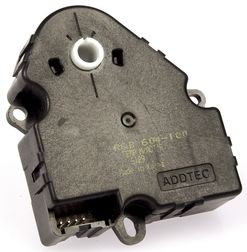
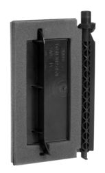
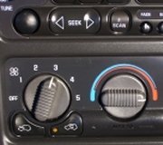
Blend door and the blend door actuator are located on the heater case (plenum).
More information
Test: no operation in all temperature settings:
Start engine and bring to normal operating temperature. Turn blower motor switch to LO position.
Turn mode selector switch to PANEL position (MAX A/C position, if A/C
equipped). Turn temperature control to full COOL position and check for cool air
discharge. Turn temperature control to full WARM position and check for warm air
discharge. Rotate temperature control from full WARM position to full COOL
position. If air temperature does not change, go to next step. If air temperature changes, system is operating properly at this time.
Turn ignition off. Remove fuse No. 5 (15-amp), located in Central Junction Box (CJB).
Check fuse condition. If fuse is okay, go to step 4. If fuse is blown, replace fuse and recheck system operation. If fuse blows again, go to next step.
Ensure ignition switch is off. Disconnect electronic blend door actuator 8-pin harness
connector C229. Disconnect temperature control switch (potentiometer) 4-pin harness
connector C217. Disconnect CJB 34-pin harness connector C242 (located under left side of instrument panel). Measure resistance between ground and CJB connector C242 terminal
No. 15 (Light Blue/Pink wire). See Fig. 6. If resistance is more than 10 k/ohms, replace
CJB. If resistance is 10 k/ohms or less, repair short to ground in Light Blue/Pink wire
between CJB and electronic blend door actuator. See WIRING DIAGRAMS. Turn ignition off. Disconnect electronic blend door actuator 8-pin harness connector C229.
Turn ignition switch to RUN position. Measure voltage between ground and blend door
actuator connector C229. If more than 10 volts exist, go to next step. If 10 volts or less
exists, repair open in Light Blue/Pink wire between CJB and electronic blend door actuator.
Turn ignition off. Disconnect electronic blend door actuator control switch 63-pin harness connector C220. Measure resistance of specified circuits between electronic blend door actuator harness connector C229 and blend door actuator control switch harness connector.
If resistance is less than 5 ohms for all wires, go to next step. If resistance
is 5 ohms or more on any wire, repair appropriate wire(s).
Measure resistance between temperature control switch terminals No. 2 (Yellow/Light
Green wire) and No. 3 (Red/Light Green wire). See Fig. 7. Temperature control switch resistance should be more than 3000 ohms in full WARM position and less than 300 ohms in full COOL position. Resistance should change gradually as temperature control switch is turned from COOL to WARM and back. If switch resistance is as specified, go to next step.
If temperature control switch resistance is not as specified, replace temperature control switch. Measure resistance of Black wire between ground and electronic blend door actuator harness connector C229 terminal No. 8. See Fig. 7. If resistance is less than 5 ohms, replace temperature blend door actuator. If resistance is more than 5 ohms, repair Black wire between ground and blend door actuator.
Please let us know happens so it will help others.
Images (Click to make bigger)
Thursday, April 15th, 2021 AT 1:45 PM
(Merged)


