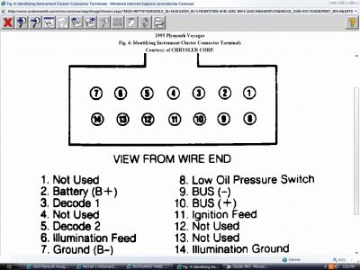
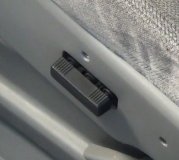
ENTERING ON-BOARD DIAGNOSTICS & SYSTEM DIAGNOSIS Electronic Instrument Cluster 1. While turning ignition on, simultaneously press TRIP and TRIP RESET buttons. The word CHEC should appear in odometer display. If there is no display, go to step 3). 2. If digits are displayed in odometer, repeat vehicle start (on-board diagnostic) sequence. If CHEC is displayed, cluster successfully entered self-diagnostic mode. Go to step 4). If an erroneous display in odometer appears, go to step 7). 3. Check all fuses. Check for ignition and battery voltage at instrument cluster connector. Check instrument cluster ground circuit. Repair voltage and ground circuit(s) as necessary. If all items are okay, replace instrument cluster. 4. Press US/M button to perform test sequence. If the word CODE appears in odometer display for 4 seconds, followed by 999 at 3 second intervals, go to step 7). If the word CODE appears in odometer display for 4 seconds, followed by 110 then 999 at 3 second intervals, replace electronic instrument cluster. 5. If the word CODE appears in odometer display for 4 seconds, followed by 921 then 999 at 3 second intervals, replace body controller. If the word CODE appears in odometer display for 4 seconds, followed by 900, 905, 920, 940 then 999 at 3 second intervals, go to next step. ELECTRONIC INSTRUMENT CLUSTER CODES 6. Check Chrysler Collision Detection (C 2 D) serial data bus using Diagnostic Readout Box (DRB). Disconnect battery. Check continuity from electronic instrument cluster to body controller and Powertrain Control Module (PCM). If no continuity exists, repair circuit(s) as necessary. See Fig. 4 . If continuity exists, replace body controller or PCM. 7. Press US/M button to perform next test sequence. All display segments should come on for 6 seconds, then 5 should appear in odometer display. If some segments do not come on, replace instrument cluster. 8. If all segments come on, select appropriate test and proceed as indicated. To test fuel gauge circuit, go to next step. To test cluster illumination, go to step 11). To test individual segments and speedometer/odometer symbols, go to step 14). 9. If fuel gauge reading and cluster asterisk are not flashing, check fuel level input signal at body controller. If resistance at fuel level input pin is less than 2 ohms or more than 150 ohms, check wiring and/or fuel tank sending unit. 10. If resistance at fuel level input pin is 2-150 ohms, fuel level input signal is okay. Disconnect fuel sensor input to body controller. If fuel gauge indicates empty, repair short to ground in fuel sensor Code Affected Circuit/Fault 110 Cluster Failure 900 Lack Of Messages 905 BUS Loop Failure 920 Lack Of Messages From Body Controller 921 Body Controller Odometer Failure 940 Lack Of Messages From Powertrain Control Module 999 End Of Test Page 1 of 2 INSTRUMENT PANEL -1995 Plymouth Voyager 8/11/2008 input. If fuel gauge indicates full, check wiring and/or fuel tank sending unit. If fuel gauge does not indicate full, replace body controller. Fig. 4: Identifying Instrument Cluster Connector Terminals Courtesy of CHRYSLER CORP. 11. Turn headlights on. If Transmission Range Indicator (TRI) or button module do not illuminate, check if other instrument panel components are lit. If other components are not lit, turn headlight switch off then on. If condition is still present, check headlight switch, wiring and illumination feed circuit to body controller. 12. If other components are lit, remove instrument cluster. Move slider (rheostat) to full brightness. Measure voltage at instrument cluster connector pin No. 6. If voltage is less than one volt, repair circuit as necessary. 13. If voltage is more than one volt, carefully pull instrument cluster mask 3-4" from cluster. Disconnect TRI and button module wiring harness connectors. Remove button module and PRNDL mechanism. Replace TRI bulb. Install button module and TRI. Connect wiring harness and install mask. 14. Press US/M button to perform next test sequence. Individual segments should be displayed in sequence, then 6 should appear in odometer display. If 2 or more segments are displayed (lit) simultaneously, replace instrument cluster. 15. If segments light individually, press US/M button to perform next test sequence. Speedometer and odometer symbols should be displayed in sequence, then 7 should appear in odometer display. 16. If 2 or more symbols are lit simultaneously, replace instrument cluster. If symbols light individually, instrument cluster is operating properly. Press US/M button to return instrument cluster to normal operating mode.

Saturday, September 26th, 2020 AT 2:41 PM
(Merged)


