I've had students with the same misconception. You're right, it's current that burns out a bulb, but what determines how much current is going to flow through it? It's voltage, (electrical pressure), and resistance, (the resistance of the bulb AND the entire rest of the circuit. Voltage isn't going to change. It's 12 volts. Resistance for the entire circuit starts with that of the bulb, period. The amount of current through the bulb, (amps = volts / resistance), will equal 12 divided by the bulb's resistance. Anything that adds resistance to the circuit will cut the amount of current. Corrosion on a switch contact adds resistance and reduces current. Frayed strands of wire increases resistance in the circuit and reduces current.
For the sake of simplifying the explanation, lets use 12 ohms for the bulb, which is real close to the actual value for a brake light bulb. Using Ohm's Law, the first thing any electronics students learns on the first day of class, current equals 12 volts divided by 12 ohms equals one amp. The is no way possible for current through that bulb to be any higher than one amp unless you increase voltage or decrease resistance. Both of those are constants. The only thing you can possibly do to change the amount of current is to change the amount of resistance in the rest of the circuit. You can lower the negligible resistance in the wires by going to larger diameter wire, but the wires already in use are sufficient. You can add resistance by introducing a corroded splice, pitted switch contacts, longer lengths of wire, etc, but that will also just reduce current. The only real way to increase current is to increase voltage with a battery charger or shorted voltage regulator. Other than that, you'll never see a bulb burn out from too much current. It's the resistance of the bulb itself that limits current.
Your comment earlier about adding a resistor is exactly correct because it will limit current flow to a safe level, but that's exactly what a light bulb is. It's a resistor. All resistors give off heat, that's why some, such as a ballast resistor in an old ignition system have to be so big. Some resistors are smaller than the head of a finishing nail. If you raise voltage high enough, and build in low enough resistance into the resistor, it will start to glow, ... And you have a light bulb. You can put a 12 ohm resistor in place of the blowing fuse and the most current flow you can possibly have will be one amp, but what good is that? Replace the blowing fuse with a 12 ohm light bulb and the most current flow you can have is still one amp, but now you get a visual clue as to how much current is flowing, and you can see immediately when you do something to remove the short.
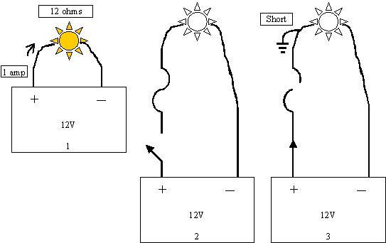
In case this explanation just made things more confusing, see if these sad drawings help:
In Figure 1, if you connect a brake light bulb right across a 12 volt battery, you get 1 amp of current flow. You can't get inside the bulb to change its resistance, and you can't change battery voltage, so that one amp is constant.
In Figure 2 we've added a switch and a fuse. Both ideally will have 0 ohms but in reality they do add a miniscule amount of resistance, but not nearly enough to talk about. Pitted switch contacts or corrosion on the fuse terminals can only add undesirable resistance which will reduce current flow.
In Figure 3, the circuit is turned on but there is a short to ground after the fuse. With 0 ohms in the entire circuit, current equals 12 volts divided by 0 ohms = infinite amps. The fuse blows.
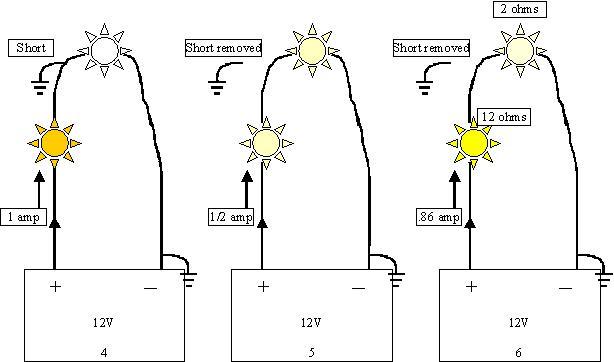
In Figure 4, I added your resistor, (my light bulb), and it's another 12 ohm bulb so again, with no other resistance in the circuit, 12 volts / 12 ohms = 1 amp. The bulb will simply be full brightness. No wasted fuses and you can see that the circuit is powered up and there is nothing else to limit current besides the resistance of the bulb.
In Figure 5 the short was located and removed. Now you have two 12 ohm bulbs in series so they total 24 ohms. 12 volts / 24 ohms = half an amp of current. At only half an amp, both bulbs will be dim. There's the convenient visual clue that you're on the right track. To find the location of the short, you can unplug harnesses, turn various switches on and off, and move wire harnesses around that could be rubbed through or laying on hot exhaust parts.
To add one more point of confusion, in this story the 12 ohm bulb in the car and the 12 ohm bulb in place of the fuse are equal in resistance so it made the math and explanation easy. In a real brake light circuit you will have two, four, or six bulbs on the car and each one will draw one amp. Again using an electronics formula, six 12 ohm bulbs in parallel equals 2 ohms. That means if you look at Figure 6, the equivalent resistance is shown. It's two ohms. You still have your test bulb in place of the fuse and it's 12 ohms. The test bulb and the rest of the circuit add up to 14 ohms. Doing the math again, current equals 12 volts / 14 ohms =.86 amps. All.86 amps flows through the test bulb and that's pretty near the normal one amp so that bulb is still going to be fairly bright. You might only see the subtle change if it occurs while you're staring at it. That.86 amps is going to be divided up equally among the six brake light bulbs. That means there will be about.14 amps flowing through each bulb, barely enough to make them glow even if you shade your eyes and look real close.
In this case when you're working in a higher-current circuit, you solve that by using a lower resistance bulb in place of the fuse. That will let more current flow so the test light will get dimmer when the short is gone and the car's bulbs will be brighter so you can see the change easier. I recommend to people to use a head light bulb in those instances. They are a little over 2 ohms so in the case of the six brake light circuit, it just happens that the head light will get half the 12 volts and be half brightness, and the brake light bulbs will also get six volts and be half brightness. That's enough voltage to see the bulbs glowing. When the brake lights glow, even real dimly, you know the short can't be present in the circuit.
Instead of a head light bulb that's rather cumbersome, a got a hold of a right rear Viper tail light harness that had five filaments in three light bulbs. I wired them all in parallel so together they draw about 4 amps. I hung that mess from the rear-view mirror so I could see it from anywhere around the car. I found a pinched trailer harness wire under the left rear tail lamp lens on a Dodge van that way. As soon as I removed a couple of screws, the tail light started to glow, then I noticed my test lights had dimmed. I also found an extra long mudflap screw run through a wiring harness by banging on the sill plate with a rubber mallet. On that car, the fuse would only blow when driving over bumpy roads. Every time I hit that sill plate, the test bulb would flash bright for an instant when the short occurred.
When you transfer all of this to a circuit that's blowing the fuse, you have to start out knowing what to expect for normal current flow. When it's a lighting circuit it's pretty easy to add up the number of bulbs in the circuit and multiply by the amount of current each one normally draws. When you get into computer circuits or motor circuits where you aren't sure of what's normal, you can use half of the fuse rating as a starting point. You have to always keep in mind that you need to tailor the test bulb to the circuit so it will be dim enough to notice when the short is gone. Take a starter solenoid circuit for example. The solenoid is so low in resistance that a single brake light test bulb will be almost full brightness when there is no defect in the circuit. That doesn't do you any good. You can go down by the starter and ground that terminal to create a short and barely see any change in your test light bulb's brightness.
If the bulb is too small, like a # 159 dash light bulb, they draw so little current that they can be almost full brightness when the rest of the circuit doesn't even have a defect. That's no help either.
Images (Click to make bigger)
Monday, March 12th, 2012 AT 1:34 PM


