Monday, October 22nd, 2012 AT 10:53 PM
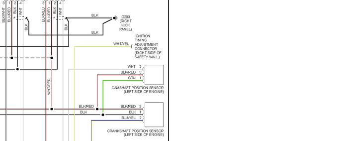
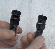
SUV was running great but broke the timing belt. I did a valve job but when done is not firing on two cylinders (same coil). Have replaced everything -- coils, ignition controller, crank and cam sensors, and the computer. I run the problem down to the connection between the crank sensor and the computer. Two of the prongs have connectivity (blue light on tester), but the third (on the dead coil) is open (no blue light on tester). However, the wire color (black with red stripe) on the bad sensor lead does not appear on the computer harness -- there is no black with red stripe wire on the computer harnerss! How the heck does the wire color change from end to end through the wiring harness fron the sensor to the computer? Anyway, to troubleshoot further I need to know which computer pin goes to the crank sensor. Also, any other idea on what could cause the problem?


