Your tech cannot get this info? Does not sound right.
Roy
Install timing belt.
(a) Install sprocket No. 2 and sprocket to crankshaft.
NOTE: Sprocket No. 2 can be identified by the absence of dowel pin.
(b) Install crankshaft pulley to crankshaft, and tighten bolt temporarily.
(c) Align the center of three lines scribed on the flywheel with timing mark on flywheel housing.
Camshaft Timing Marks, Left Side (DRIVER'S SIDE)
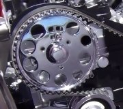
(d) Align timing mark on camshaft sprocket LH with notch in belt cover.
(e) Attach timing belt No. 2 to crankshaft sprocket No. 2, oil pump sprocket, belt idler, camshaft sprocket, in that order, avoiding downward slackening of the belt.
(6) Loosen tensioner No. 2 tightening bolt (D) by 1/2 turn to apply tension to belt.
(f) Push timing belt by hand to ensure smooth movement of tensioner.
(g) Apply the specified torque to camshaft sprocket in counterclockwise direction using BELT TENSION WRENCH. While applying torque, tighten tensioner No. 2 bolt (D) temporarily, then tighten bolt (C) temporarily.
NOTE: When torquing sprocket, be extremely careful not to apply excessive force to it Excessive belt tension will greatly reduce belt life.
Belt Tension: 147 - 245 N-m (33 - 55 ft-lb)..
Torque to cam sprocket: 24 - 25 N-m (18 ft-lb).
(h) Tighten bolt (D) and bolt (C) in that order, to the specified torque.
Tightening torque:
17.2 - 20.1 N-m (1.75 -2.05 kg-m, 12.7 - 14.8 ft-lb).
(i) Ascertain that flywheel timing mark and camshaft sprocket LH timing mark are in their normal positions.
(j) Turn crankshaft one turn clockwise from the position where timing belt No. 2 was installed, and align the center of three lines scribed on the flywheel with timing mark on flywheel housing.
(k) Align timing mark on camshaft sprocket RH with the notch in belt cover.
(l) Attach timing belt to crankshaft sprocket and camshaft sprocket, avoiding slackening of belt on the upper side.
(m) Loosen tensioner bolt (B) 1/2 turn to apply tension to belt.
(n) Push timing belt by hand to ensure smooth tensioner movement.
(o) Apply the specified torque (same as camshaft sprocket LH) to camshaft sprocket RH in counterclockwise direction using BELT TENSION WRENCH. While applying torque, tighten tensioner No. 2 bolt 3 b. Temporarily, then tighten bolt a temporarily.
(p) Tighten bolt (B) and bolt (A) in that order, to the specified torque.
Tightening torque:
17.2 - 20.1 N-m (1.75 - 2.05 kg-m, 12.7 - 14.8 ft-lb).
(q) Make sure that flywheel timing mark and camshaft sprocket RH timing mark are in their normal positions.
(r) Remove crankshaft pulley.
NOTE: Do not remove sprocket with crankshaft pulley.
Install belt cover FR seal, belt cover RR seal, and belt cover plug to belt cover FR, then install belt cover FR to cylinder block.
NOTE: Before installing belt cover, ensure that no foreign matter such as nut or washer is in it.
Install belt covers LH and RH.
Install belt cover plate. TURBO model]
Install crank pulley to crankshaft using FLYWHEEL STOPPER (498277000) [manual transmission model] or DRIVE PLATE STOPPER (498497000) [automatic transmission model] to lock crankshaft. Tightening torque:
89 - 107 N-m (9.1 - 10.9 kg-m, 66 - 79 ft-lb).
Install water pump pulley and pulley cover to water pump assembly, and tighten nuts temporarily.
Install oil level gauge and gauge guide. Apply engine oil to 0-ring beforehand.
Connect lead to oil pressure switch.
Install V-belt and apply proper tension to the belt.
Tighten water pump pulley mounting nuts or bolts to the specified torque. Tightening torque:
9.1 - 10.5 N-m (0.93 - 1.07 kg-m, 6.7 - 7.7 ft-lb).
SPONSORED LINKS
Sunday, November 11th, 2012 AT 4:04 AM


