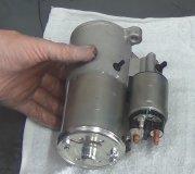
You actually still have the common sense, simple starter circuit with no silly computers involved. We can do all the diagnosis right from the starter relay's socket. The goal right now is to keep the problem acting up so we can figure out the cause. You can use a digital voltmeter, but for this type of problem, a test light is faster and could be more accurate.
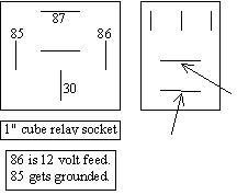
Ground your voltmeter's negative probe or the test light's clip lead, then remove the starter relay from its socket. Probe the four terminals to see if one has twelve volts all the time. I think you will have the one inch cube relay as shown on the left of my nifty drawing. Do not worry about the terminal numbers right now. This group of tests should only take a minute. Also, be careful to not poke the test probe into the terminals as that can spread them, then you could have intermittent problems in the future. The starter relay is shown on the fuse box cover. If that is missing, I will look up the layout for you.
You must find twelve volts on one of the four labeled terminals. If you do, have a helper turn the ignition switch to "crank", then check for twelve volts on the other three terminals. If you do not find that, we will need to look at the ignition switch and its connector. This twelve volts should come and go when the helper switches the ignition switch between "crank" and released.
Now, move the meter's or test light's ground clip to the battery's positive terminal. We will be testing for good ground circuits. Probe the two remaining terminals in the relay socket. One of them should show continuity all the time. That is reading to ground through the starter solenoid. The last one should also read to ground, but one of those will go open circuit when you shift to "reverse" or "drive". If you do not find that terminal, the neutral safety switch is suspect.
Image (Click to make bigger)
SPONSORED LINKS
Saturday, May 26th, 2018 AT 7:48 PM


