Wiring schematics for flasher unit and hazard lights needed

Tiny
MICHAEL LYNCH2
  • MEMBER
  • 1999 MAZDA 323
  • 1.6L
  • 4 CYL
  • 2WD
  • AUTOMATIC
  • 150 MILES
Hi Guys, I have bought the car listed above that's causing me some drama's. The indicators flash both sides of the car like hazard lights when you move the indicator stalk up or down. Nothing else is malfunctioning all lights work. There are no blown globes etc. If you turn on the hazard switch by itself it works as it should. If you turn on the hazard switch with indicators on it makes no difference all the hazard lights remain on.
Okay, so that's the problem however in investigating all the components I have made a few discoveries. The car has had an aftermarket alarm system that has been cut out of the car sometime in its history. Worse it has a Central locking unit that doesn't work and when the alarm system has been hacked out of the circuitry they have cut wires to the central locking unit. I have tested all the components as follows:

The flasher unit which is a 3 pin unit works fine.
The hazard switch which is a 9 pin unit works fine.
The indicator stalk control switch works fine.

There is no issues with the connector plugs to the dash cluster. I've taken them out of their sockets and given them a clean with contact cleaner.

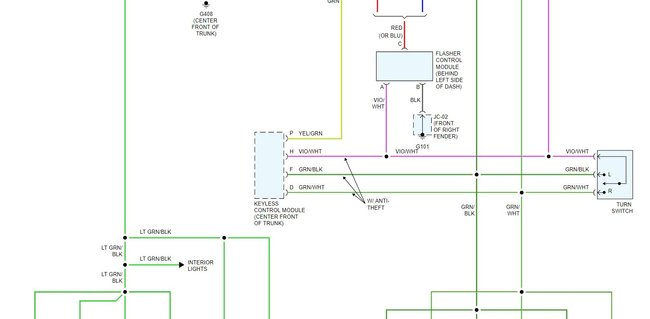
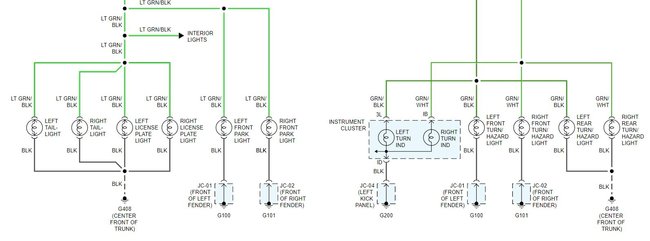
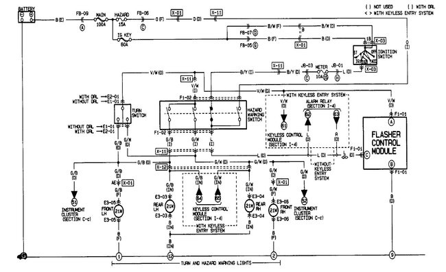
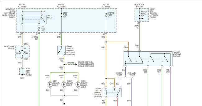
My suspicion is that I have lost an earth somewhere and it probably is because of the vandalism caused by the bad removal of the alarm system and subsequent cutting of various other wires. So what I need is some wiring schematics incorporating all of the components mentioned so I can do some real detective work because it's very difficult without them to trace the color coded wires and know what should be there and what isn't. I've got a 2002 wiring diagram but it is completely different as it uses a multi pin electronic flasher and a 2 pin hazard switch so I'm not able to use it. Would really appreciate your help.
Thanks
Friday, June 4th, 2021 AT 1:30 AM
3 Replies

Tiny
STEVE W.
  • MECHANIC
  • 13,449 POSTS
While it could be a ground I would also look close at whatever they reconnected after removing the aftermarket pieces. Attached are both versions of the wiring for the Mazda in question. I can see things getting crossed up when Mazda used similar wire colors for both sides of the system.
Was this
answer
helpful?
Yes
No
+1
Friday, June 4th, 2021 AT 5:51 AM
Tiny
MICHAEL LYNCH2
  • MEMBER
  • 23 POSTS
Hi Steve,

Thank you for these it should help a lot. Your right in regards to the color coding being so similar one side to the other. Your brain gets scrambled when you've looked at it too long without the schematics.
I still have differences in regards to both the color codes in the car and the codes shown on the diagrams but I'm sure I can work these out.
The only other problem I see on these diagrams is they are showing a hazard switch with only 6 pins and mine has 9 pins. 8 pins are being used.
So there are 2 extra wires but I hope I can rationalize these somehow when I have another look tomorrow. I will let you know how I get on. Oh also they didn't put anything back in place. Just cut the wires and left them dangling under the dash so it is really important to have the schematics.
Cheers
Was this
answer
helpful?
Yes
No
Friday, June 4th, 2021 AT 6:47 AM
Tiny
STEVE W.
  • MECHANIC
  • 13,449 POSTS
There are a few different build versions of that car depending on which plant it came from. On the missing pins, that is common on some wiring diagram layouts if those pins are not used as part of the system in the diagram. Say say there is a switch for a door lock that has 3 wires and then 2 wires for lighting the switch, the lighting connections may not be shown ii the diagram for the door locks.
Was this
answer
helpful?
Yes
No
+1
Friday, June 4th, 2021 AT 8:28 AM

Please login or register to post a reply.

Sponsored links