Timing diagram needed?

2015 HYUNDAI SANTA FE
18,902 MILES
Avatar
ANDRIN ATEM
  • MEMBER
  • 393 POSTS
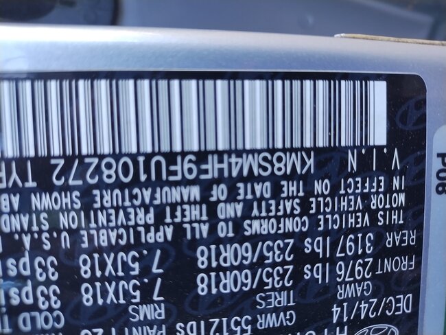
I got fault code p0340 intake camshaft sensor bank 1. Sensor has been replaced twice, same code, swap positions, fault remains on same bank 1. Please can I have the timing diagram. This will help me to verify timing. V6-3.3L Vin. KM8SM4HF9FU108272

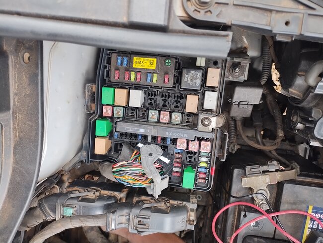
Also if I can get a screenshot of the compositions from above.
Sep 23, 2024 at 4:20 AM
Advertisement
Avatar
STRAILER
  • CERTIFIED EXPERT
  • 53,855 POSTS
Here is the procedure to set the timing chain marks, remember that after the timing marks are lined up and if you turn the engine over they will not be lined up again. Also, there are marks on the chains to help with the crankshaft to camshaft alignment. Check out the images (below). Please let us know what happens.
Sep 23, 2024 at 11:40 AM
Avatar
ANDRIN ATEM
  • MEMBER
  • 393 POSTS
Please can I have pinout Diagram for the vehicle listed above (GDI) by intake camshaft sensor pin out diagram, or signal volts.
Sep 23, 2024 at 12:29 PM (Merged)
Advertisement
Avatar
STRAILER
  • CERTIFIED EXPERT
  • 53,855 POSTS
Sure, here is the pinout and wiring diagrams for the camshaft sensors with the testing procedures. Check out the images (below). Please let us know what happens.
Sep 23, 2024 at 12:29 PM (Merged)
Avatar
ANDRIN ATEM
  • MEMBER
  • 393 POSTS
Hi Ken, please correct me if I am wrong, base on these diagrams you just sent, my readings goes as follows. Pin 1 has 5.6 volts. Pin 2. 4.86 volts, pin 3 has 4.6 volts, with ignition on and female connector discounter and these are their results.
Sep 23, 2024 at 2:00 PM
Avatar
ANDRIN ATEM
  • MEMBER
  • 393 POSTS
Normal as I know, all 3 pin sensors, has a grand power and signal, but I. This case is not same, all 3 pins got voltages even when disconnected. What can you explain?
Sep 23, 2024 at 2:01 PM
Avatar
ANDRIN ATEM
  • MEMBER
  • 393 POSTS
Except for the camshaft sensor on banm 2 which signals are. Pin 5.6 volts, Pin 2 no volts, pin 3 4.6volts, ignition on, but once the connector is fitted to the sensor, the pin 2 gets 4.5volts coming as signal to the ECU, with ignition on engine off.
Sep 23, 2024 at 2:05 PM
Avatar
ANDRIN ATEM
  • MEMBER
  • 393 POSTS
I even swapped ECU, since this model does not require immobilizer, it's security free, yet the car still has same faults.
Sep 23, 2024 at 2:06 PM
Avatar
ANDRIN ATEM
  • MEMBER
  • 393 POSTS
Hi Ken, thanks for the diagrams, it has put me in track close in revolving the the problems I have. Please may I have the fuse box ground and power diagram,.? From your previous diagrams, I ha e realized that, none of the sensors got ground signal coming to it.
Sep 24, 2024 at 5:33 AM
Avatar
ANDRIN ATEM
  • MEMBER
  • 393 POSTS
If I find out what ground wire is supposed for the sensors, that will solve my problems
Sep 24, 2024 at 5:40 AM
Avatar
STRAILER
  • CERTIFIED EXPERT
  • 53,855 POSTS
Sure, the brown and black wires are the sensor grounds to the ECU.
Sep 24, 2024 at 2:04 PM