Transmission Range Sensor connector wiring issue?

2002 FORD WINDSTAR
200,000 MILES • 3.8L • 6 CYL • 2WD • AUTOMATIC
Avatar
ELGUAPOTORRES33
  • MEMBER
  • 10 POSTS
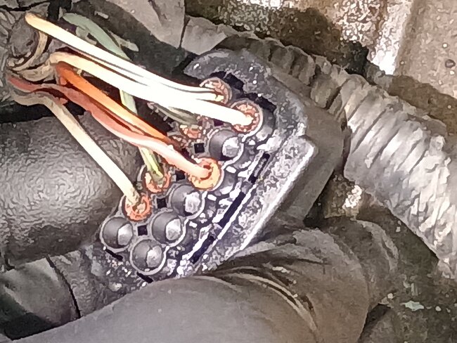
My Transmission Range Sensor wiring harness was all frayed and damaged, so I replaced all the wires and terminal pins understand what but unfortunately, the photo I took for just this reason didn't come out, very clear. So, I don't know the proper order of the wiring connections.

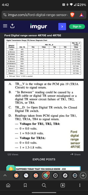
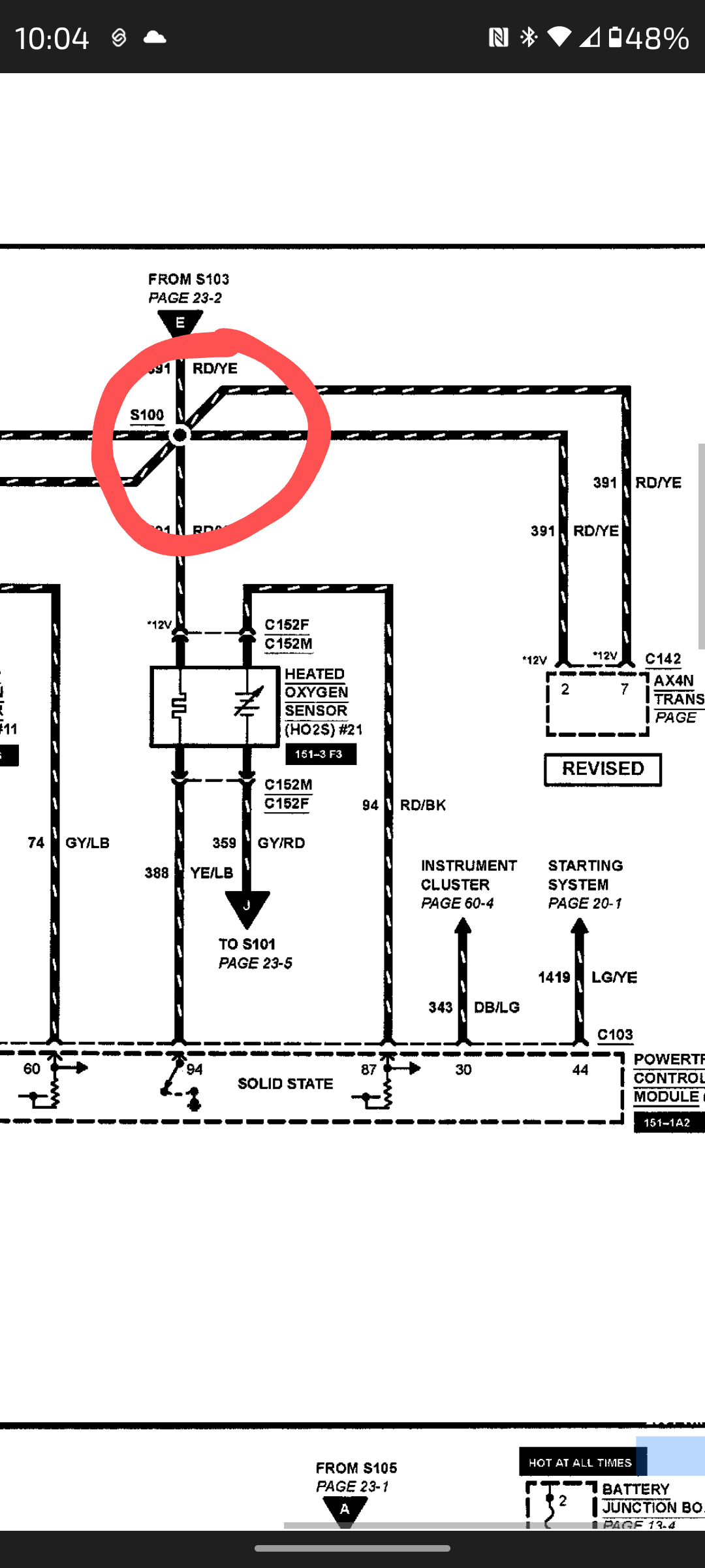
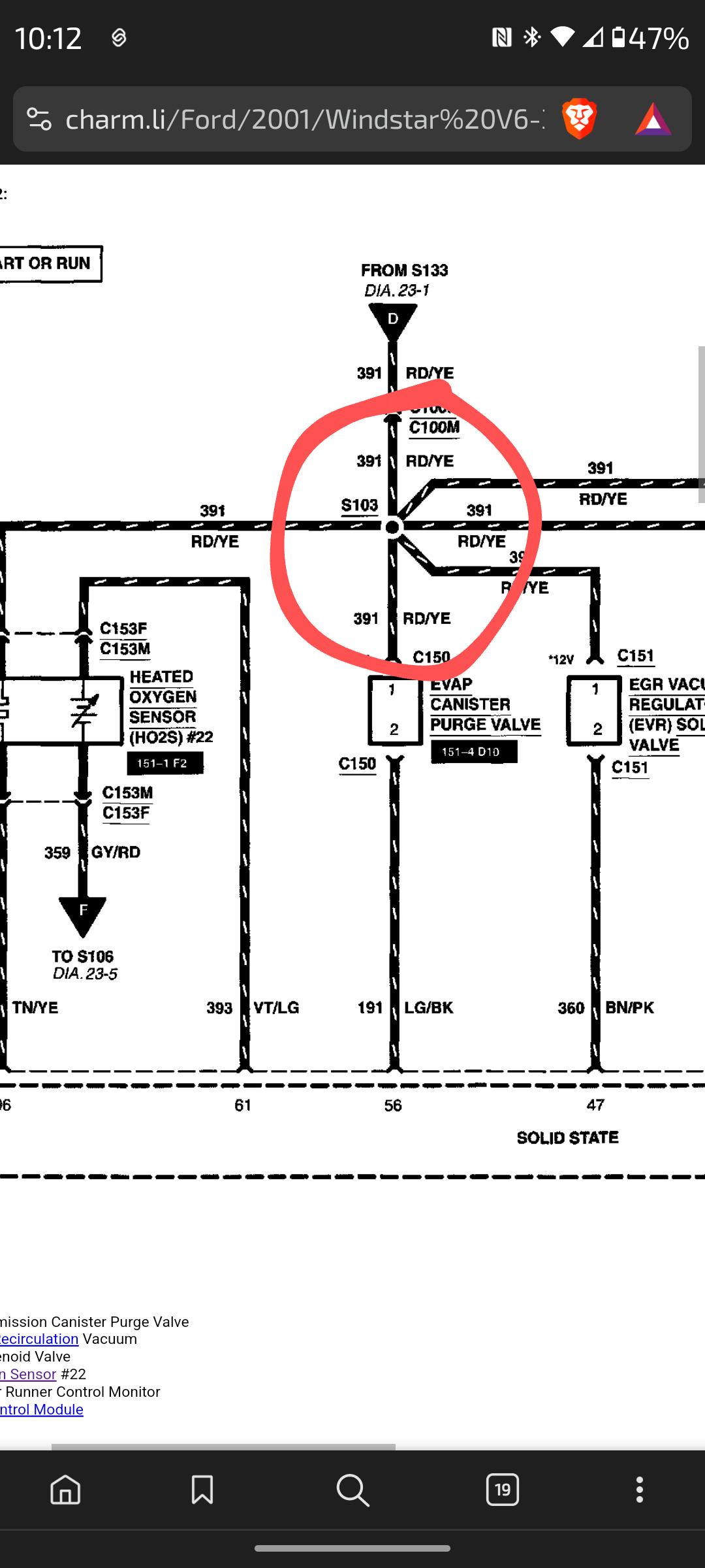
I've looked for wiring diagrams and I thought I found the right one but as I followed it exactly and reverse is now in parks spot it's clear I don't have the correct pinout order.
Any help would be really appreciated as just guessing the right order, I have a 12-pin connector, and though it only uses seven wires, five on the top, two on the bottom, trial and error could take me well into retirement age.

By the way I know the proper spaces just not which goes in said holes.

Thank you so much in advance!
Oct 28, 2024 at 11:34 PM
Advertisement
Avatar
STRAILER
  • CERTIFIED EXPERT
  • 53,855 POSTS
Sure, here is the connector view so you can see which wires go where for the gear range sensor (neutral safety switch). Check out the images (below). Let us know if you need anything else.
Oct 29, 2024 at 11:40 AM
Avatar
ELGUAPOTORRES33
  • MEMBER
  • 10 POSTS
This is awesome, thank you so much!
I do have one, now it seems weird, question: would you have any idea why my TRS (NSS) would have had a 7th wire in addition to the 6 in the provided image? I've attached the poor, photo of the connectors original state, I. E. before I began any cleanup.
As it stands, I guess I'll just attempt to replicate the diagram, but it does leave me a bit concerned (as with most everything on this infernal work vehicle).

Thank you very much again!
Oct 29, 2024 at 12:00 PM
Advertisement
Avatar
ELGUAPOTORRES33
  • MEMBER
  • 10 POSTS
This is awesome, thank you so much!
I do have one, now seems weird, question: would you have any idea why my TRS (NSS) would have had a 7th wire in addition to the 6 in the provided image? I've attached the, poor, photo of the connectors original state, I. E. before I began any cleanup.
As it stands I guess I'll just attempt to replicate the diagram but it does leave me a bit concerned (as with most everything on this infernal work vehicle).

Thank you very much again!
Oct 29, 2024 at 12:07 PM
Avatar
ELGUAPOTORRES33
  • MEMBER
  • 10 POSTS
Sorry one additional thought, now that I'm physically looking at connector: all of the "not used" seats have a solid plastic barrier preventing, I assume, moisture, or incorrect placement from getting through... It's definitely possible the previous Dr. Frankenstein type of mechanic / owner punctured it while adding a superfluous? 7th wire but it sure adds to my confused concern.

Thanks again by the way!
Oct 29, 2024 at 12:17 PM
Avatar
ELGUAPOTORRES33
  • MEMBER
  • 10 POSTS
Sheesh I apologize but if it helps, the 7th wire in question is white and black and at least does seem to originate from the same branch of the feeder harness.
Oct 29, 2024 at 1:48 PM
Avatar
STRAILER
  • CERTIFIED EXPERT
  • 53,855 POSTS
Yep, the wht/blk wire goes the PCM, here are all of the wires to the gear range sensor so you can see how the system works. Check out the images (below). Please let us know what happens.
Oct 30, 2024 at 9:37 AM
Avatar
ELGUAPOTORRES33
  • MEMBER
  • 10 POSTS
I really appreciate your reply and time, but now I'm a bit more confused; I actually did see that diagram before but you'll note that the first diagram you sent me had only 6 wires coming to connector, and I have all 6 of those colors / open pin seats (with no white / black wire indicated) but then the bottom diagram seems to show only 5 wires, now including the w/b wire and seemingly with just 4 of the others, but in a different order?
Oct 30, 2024 at 11:34 AM
Avatar
STRAILER
  • CERTIFIED EXPERT
  • 53,855 POSTS
Okay, I looked up the gear range sensor for a 2003 and it has 7 wires, please check this one out.
Oct 31, 2024 at 12:44 PM
Avatar
ELGUAPOTORRES33
  • MEMBER
  • 10 POSTS
Ahhh, thank you so much! That makes all the sense now, I truly appreciate your assistance, and patience! I'll confirm the fix tomorrow but I'm certain we're in business now.
Oct 31, 2024 at 3:01 PM
Avatar
STRAILER
  • CERTIFIED EXPERT
  • 53,855 POSTS
That is good to hear, let us know if you need anything else.
Nov 1, 2024 at 10:15 AM
Avatar
ELGUAPOTORRES33
  • MEMBER
  • 10 POSTS
Hello! Well, this issue continues to be a thorn in my side (I've just been so busy working I've had no choice but to use a wasteful rental).
Anyhow to date I ended up buying a brand-new connector harness, and ultimately a new TRS, all installed extremely carefully and to spec (including numerous shifter, alignment adjustments until exactly perfect) yet the dreaded flashing OD/limp mode continue.

I just ran through a multimeter diagnostic I found (see attached) and see what I believe to be the issue:
While in park the White/Black wire, TR4, reads 9volts instead of 0 as the chart indicates it should. I followed back and saw no signs of even a chance of any further wire frays or the sort, as I'm mediocre at best when it comes to electrical, I hoped you might have some semi specific steps for me to figure out why the errant voltage.

I should add, one main reason I'm confident of the install is dead center shifter alignment, starts only in P or N, and reverse lights illuminating only in R.

Please let me know if I failed to provide any necessary info; and thank you in advance, and retrospectively in fact, for all of your help, it is super appreciated!
Mar 6, 2025 at 5:26 PM
Avatar
STRAILER
  • CERTIFIED EXPERT
  • 53,855 POSTS
Is reverse is still in the park spot?
Mar 7, 2025 at 9:28 AM
Avatar
ELGUAPOTORRES33
  • MEMBER
  • 10 POSTS
No. It never was (though I did read a similar post where that was the case), in my case the worst the new install ever seemed had all notches about half a letter shifted to the right of each dead center respectively.
This has been rectified with some slight tweaks to the shifter cable along with the Transmission Range Sensor. Now all are pointed perfectly dead center when shifting up or down the tree.
Mar 7, 2025 at 10:57 AM
Avatar
STRAILER
  • CERTIFIED EXPERT
  • 53,855 POSTS
Good job. Yep, white/black wire, TR4 should read 0 volts, did you test it with the gear range sensor plugged in or unplugged? This circuit is a simple reference connection. I would double check to see if you are connected to the correct wire.
Mar 8, 2025 at 9:29 AM
Avatar
ELGUAPOTORRES33
  • MEMBER
  • 10 POSTS
I have had ongoing issues, most mechanical, but now have solved down to some frayed electrical harness/breakouts. Specifically this splice junction sad totally melted to unrecognizable mess so after cutting out and attempting to out back together I'm left with a super elementary I'm sure question: it reads to me like the splice point is just 3 like wires in, 3 like wires out. I stupidly, again I'm sure, thought we'll how is that different than just going 1 to 1 right through (electrical is by far my weakest as you can tell). SO long question still long, how should I be going about, propey recreating what's expected here? All of my searching just keeps showing splicing 2 into 1 but that can't be the answer as I'm 3:3.
Thank you so much!
Apr 13, 2025 at 10:10 AM (Merged)
Avatar
ELGUAPOTORRES33
  • MEMBER
  • 10 POSTS
Sorry the final 2 are the, same, spot in question, edit wouldn't prophet allow deleting an image
Apr 13, 2025 at 10:10 AM (Merged)
Avatar
STEVE W.
  • CERTIFIED EXPERT
  • 15,116 POSTS
Those are a splice point where all of the wires are connected because they share the same 12 volt power feed. So all of them need to be connected into one connection. In older vehicles they did this by crimping a ring terminal to each wire, then those were riveted into a star or similar, then painted with sealer and wrapped in tape. In modern cars they take a crimp style butt connector, stuff the wires in from both sides and crimp them in. When I make a crimp I do it similar to the modern OEM. In this case I would take three wires to each side. Slide a piece of self sealing heat shrink up one side, then crimp on an un-insulated butt connector. Crimp it tight. Then insert the three from the other side and crimp it. Now a coat of liquid tape just to fill the voids. Let that air dry long enough that the heat shrink will slide over it. Then heat up the tubing until it shrinks and the adhesive sealer squeezes out. Let it cool. Then if I'm building a harness it gets wrapped with a cloth based tape. If it's in a vehicle it gets scotch 33 wrapped and put back into the loom.
Similar to the way you see the crimps done in these vids.

https://www.youtube.com/watch?v=LHcKVwJ3Ees
https://www.youtube.com/watch?v=RkfMiqmJgaI

Apr 13, 2025 at 10:10 AM (Merged)