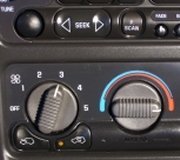
Temperature Cable Removal and Installation
NOTE:Because the cable and the cable housings have fixed lengths, it is impossible to make a temperature cable adjustment.
Remove the glove box.
If a malfunction is suspected, verify the proper operation of the controller and the mechanical doors for the heater/air distributor case assembly.
Removal
Disconnect the negative battery cable.
The heater/air distribution case linkage also cannot be adjusted.
Disconnect the cable retainer from the blower housing.
Slide the cable eyelet off the post on the temperature door lever.
Fig. 20: Sliding Cable Eyelet Off Post On Temperature Door Lever
Courtesy of SUZUKI OF AMERICA CORP.
Remove the audio system trim plate. Refer to INSTRUMENT CLUSTER TRIM PANEL REMOVAL.
Remove the four controller retaining screws.
Pull out the controller to provide clearance for removal of the temperature control cable.
Disconnect the temperature control cable eyelet from the post on the controller.
Snap the cable housing connector out of the slide position on the controller.
Fig. 21: Snapping Cable Housing Connector Out Of Slide Position On Controller
Courtesy of SUZUKI OF AMERICA CORP.
Installation
Install the temperature control cable eyelet to the post on the controller.
Snap the cable housing connector to the slide position on the controller.
Fig. 22: Snapping Cable Housing Connector To Slide Position On Controller
Courtesy of SUZUKI OF AMERICA CORP.
Gently insert the controller into position on the center console.
Install the four controller retaining screws.
Tighten the controller retaining screws to 4 N.M (35 lb-in).
Install the temperature control cable eyelet to the post on the temperature door lever.
Snap the cable retainer to the blower housing.
Fig. 23: Snapping Cable Retainer To Blower Housing
Courtesy of SUZUKI OF AMERICA CORP.
Move the temperature control to verify the smooth operation and function of the door and the cable.
Install the instrument cluster trim panel. Refer to INSTRUMENT CLUSTER TRIM PANEL INSTALLATION.
Connect the negative battery cable.
Operate the heating and cooling systems to verify proper function.
Install the glove box. Refer to GLOVE BOX INSTALLATION.
SPONSORED LINKS
Thursday, April 22nd, 2010 AT 4:10 AM


