When the transmission is shifted into drive the engine shuts off?

Tiny
REDBONE
  • MEMBER
  • 2003 BUICK RENDEZVOUS
  • 3.4L
  • 6 CYL
  • 2WD
  • AUTOMATIC
  • 30,000 MILES
Car runs smoothly, then when I put it in drive it stalls, sometimes it won't start right away, let sit for a couple minutes then it will start. When I put it drive it stalls immediately reverse it doesn't stall. What could cause this?
Friday, May 31st, 2024 AT 11:27 AM

5 Replies

Tiny
AL514
  • MECHANIC
  • 4,449 POSTS
Hello, have you had the engine computer scanned for any diagnostic trouble codes? I'm sure there would be some fault the computer is picking up on. Start with that, AutoZone or some local parts store should be able to scan it for you for free. Make sure to write down any trouble codes and what modules the codes are stored in. This could be a sensor glitching out and the ECM is misinterpreting the data, causing a stall out. Could be an issue with the idle air control valve, etc. Sounds like the engine is not liking any load being put on it. This vehicle has a Mass air flow sensor and a MAP sensor, so it's measuring incoming air as well as manifold pressure, so it should set some type of code. If there's any type of lean running condition codes, that could point to a fuel pressure issue, but more information is needed.

Here are a few guides to go through:

https://www.2carpros.com/articles/checking-a-service-engine-soon-or-check-engine-light-on-or-flashing

https://www.2carpros.com/articles/stall-at-idle

https://www.2carpros.com/articles/engine-stalls
Was this
answer
helpful?
Yes
No
Friday, May 31st, 2024 AT 12:09 PM
Tiny
REDBONE
  • MEMBER
  • 96 POSTS
I retrieved the codes and this what I got U1000, P0040, PO449, B3857, B2603 and B2533. I checked fuel pressure, timing, and battery all good. The car will idle for 10 to 20 minutes then stall. The car even ran for 10 minutes while in drive then stalled. The car had to sit for 8-10 mins before I could get it to start again.
Was this
answer
helpful?
Yes
No
Saturday, June 1st, 2024 AT 1:13 PM
Tiny
AL514
  • MECHANIC
  • 4,449 POSTS
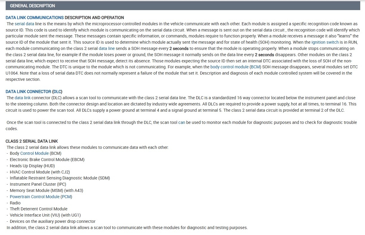
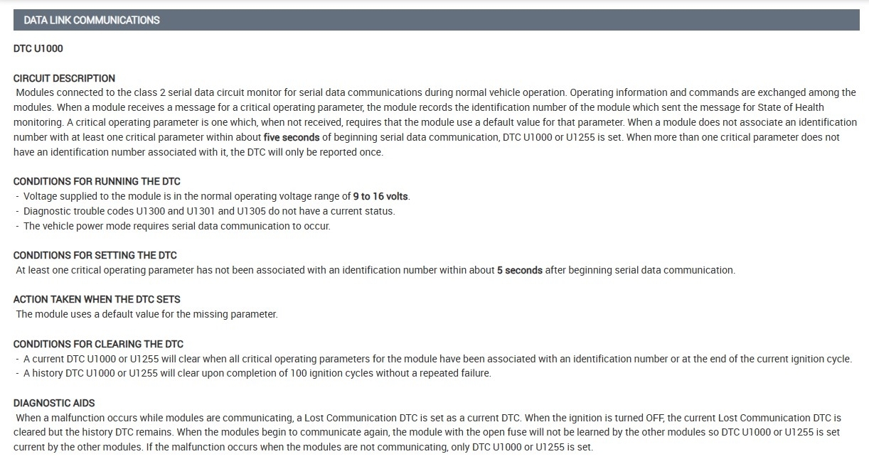
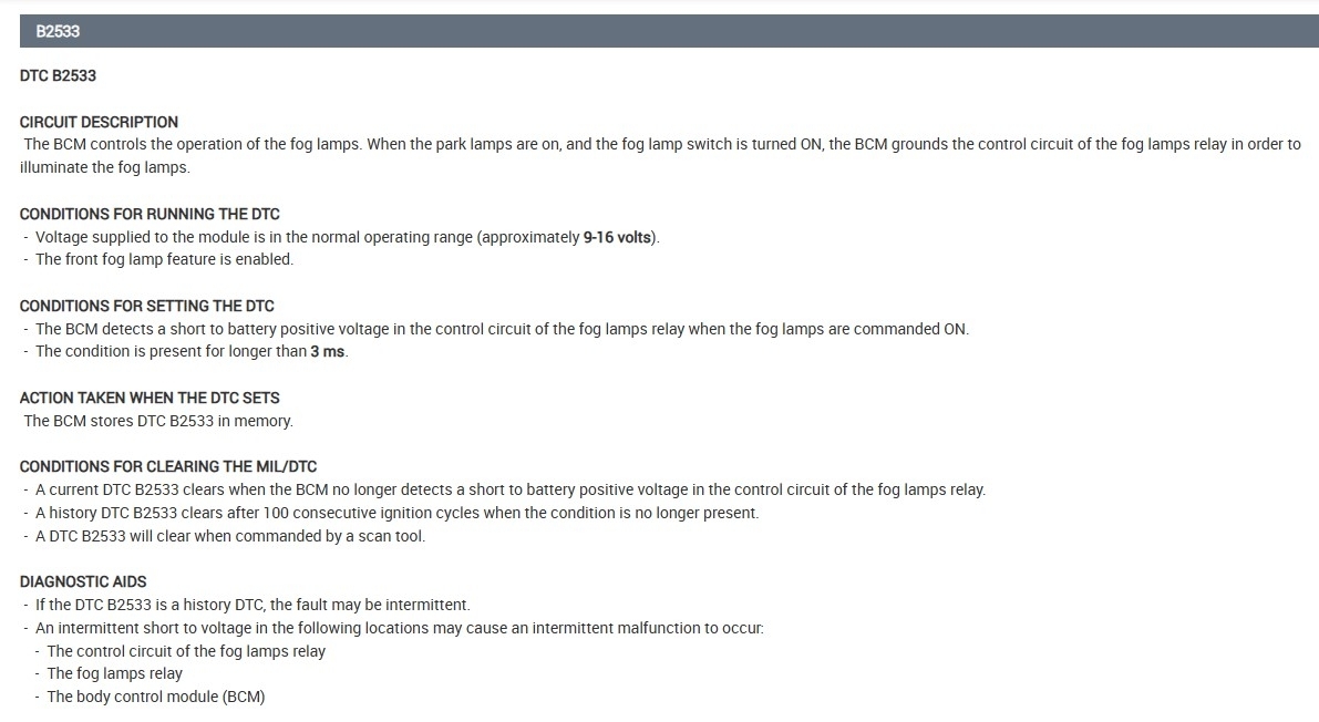
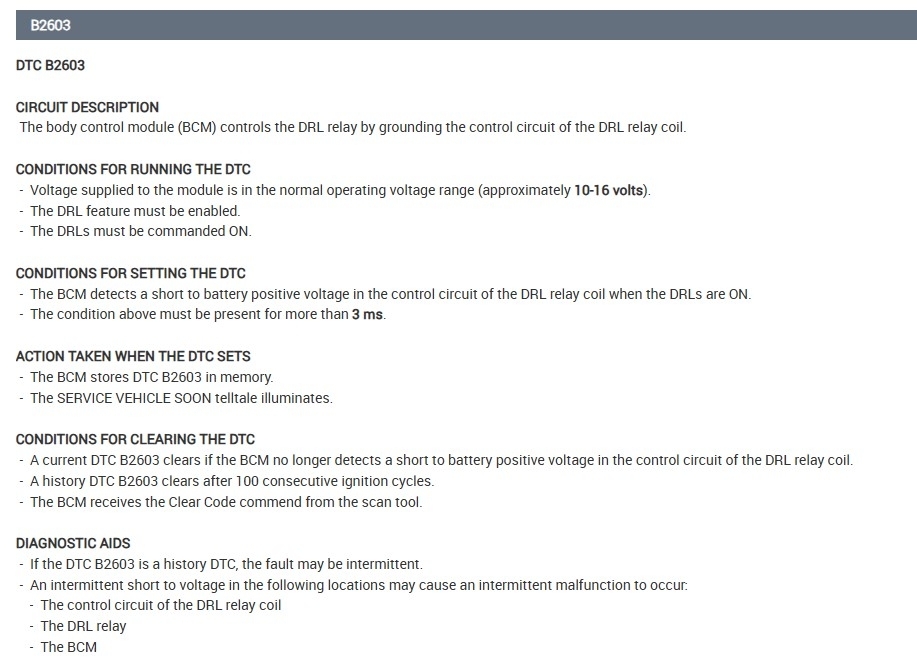
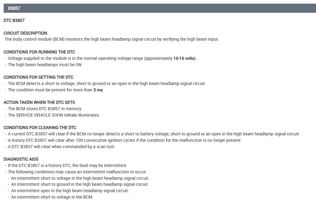
Okay, well I don't see any service info on a P0040, but the U1000 code is a network communications code, was that set in the engine computer (PCM)? Usually a module(s) will set this code when there is another module offline that the rest are not seeing, so they are pretty much telling on other modules that they are no longer able to see a specific module on the network, and this code will set. The p0449 is a Evap Vent valve control circuit code or valve issue. And the B codes are all related to the Body Control module and have to do with the headlamps, daytime running lights and fog lamp relay control.

If the U1000 was set in the BCM, then we could suspect it is losing communications with possibly the engine computer (PCM) and that's causing your stalling issue, or the other way around. This network uses a "State of health" signal from each module and once that signal drops out, a U code will be set.
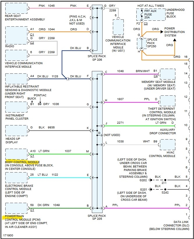
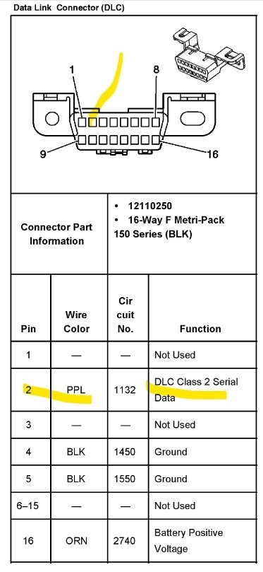
The 2nd diagram is about U communications codes. It sounds like you had the entire vehicle scanned for codes, I've added the B codes just so you have them (diagrams 3, 4, 5).

You should also notice if the Check Engine Light does not come on during Key On while the fault is occurring, if the check engine light does not come on, the PCM is down,

But you can approach this in a couple different ways, if you have your own scan tool that can try to communicate with the PCM during the fault, so after the stall out, and if you cannot communicate with it or read live data you'll know that the PCM is dropping out of the network for whatever reason, bad solder joint on the circuit board, or pin fitment issue in its connector, etc.
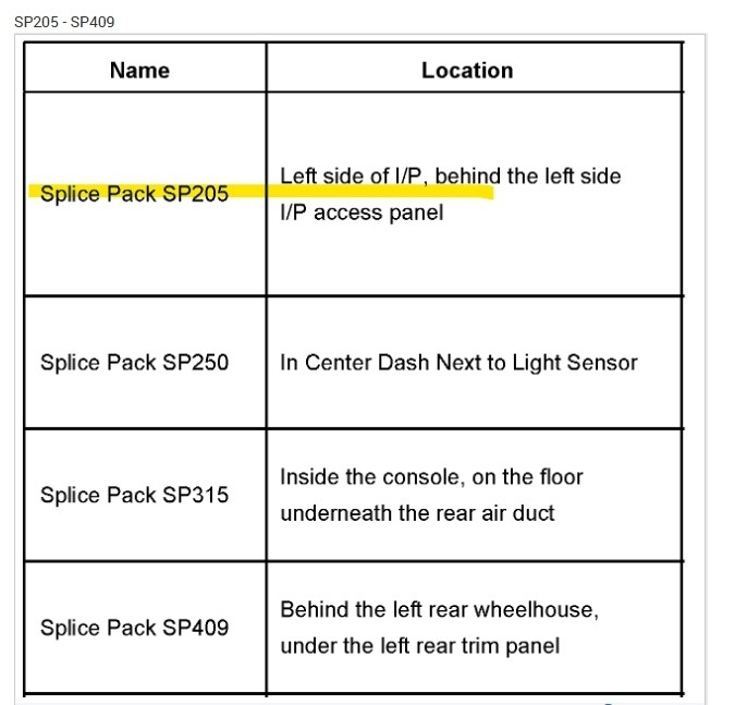
Or you can find the 2 Splice Packs SP206 and SP205, GM makes it really easy, all the modules meet up in the splice packs and are all connected by a comb that shorts them all together. Where you can de-pin a certain wire and check it for a voltage signal,

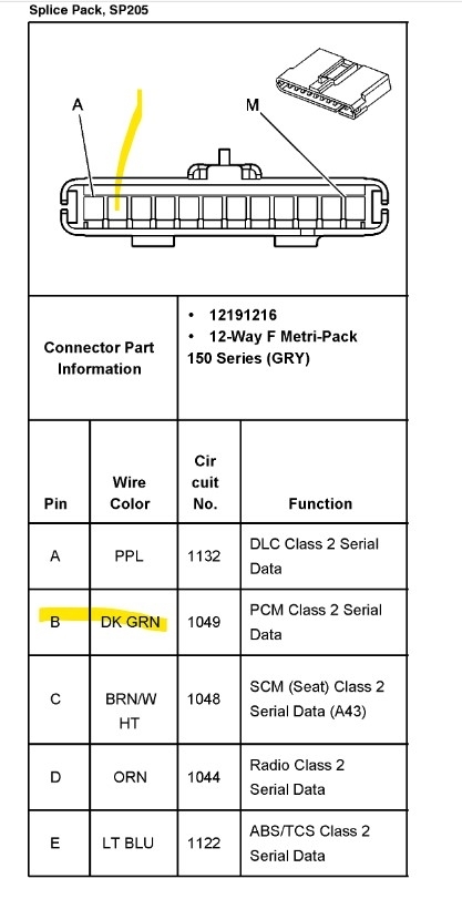
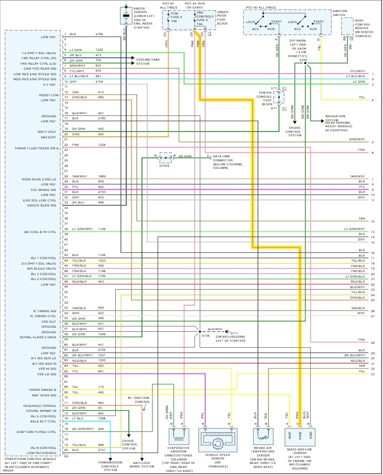
So, for example, on Splice pack 205, you'll want to check the Dark Green wire (label B -PCM) for a voltage signal,
This year it's stating a 9-14volt range, SP205 is down on the driver side lower dash, usually just to the left of the data link connector.
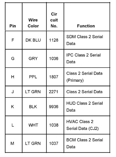
Diagrams 6, 7, 8, 9 are for the network, SP205 and its location, it's easier to first see if you can communicate with the PCM via a scan tool, unless the U1000 was setting in a different module, in some cases a bad module will pull down the entire network, either shorting it to ground or power.

Since you have a 10min or so window it's best to be set up ahead of time for testing, so when it stalls out you can quickly check for any voltage activity on the Dark Green wire (B) for the PCM.

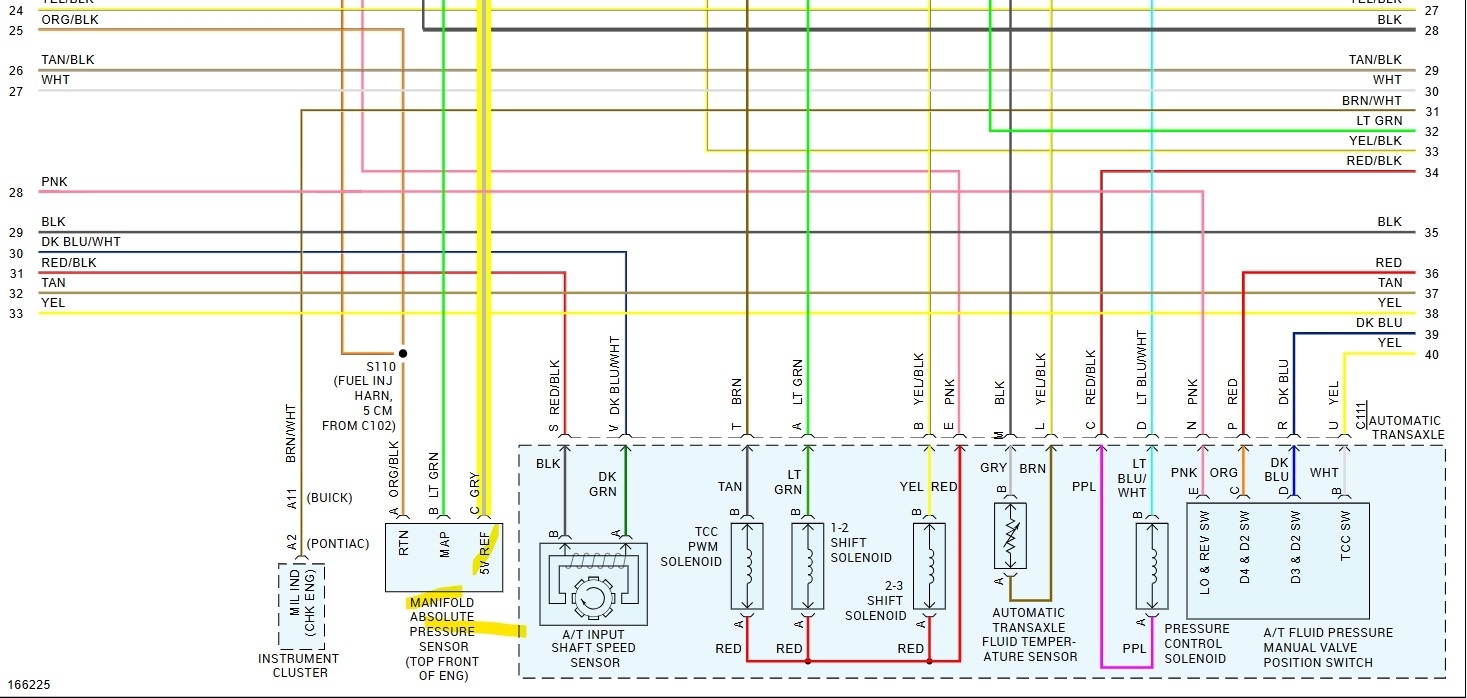
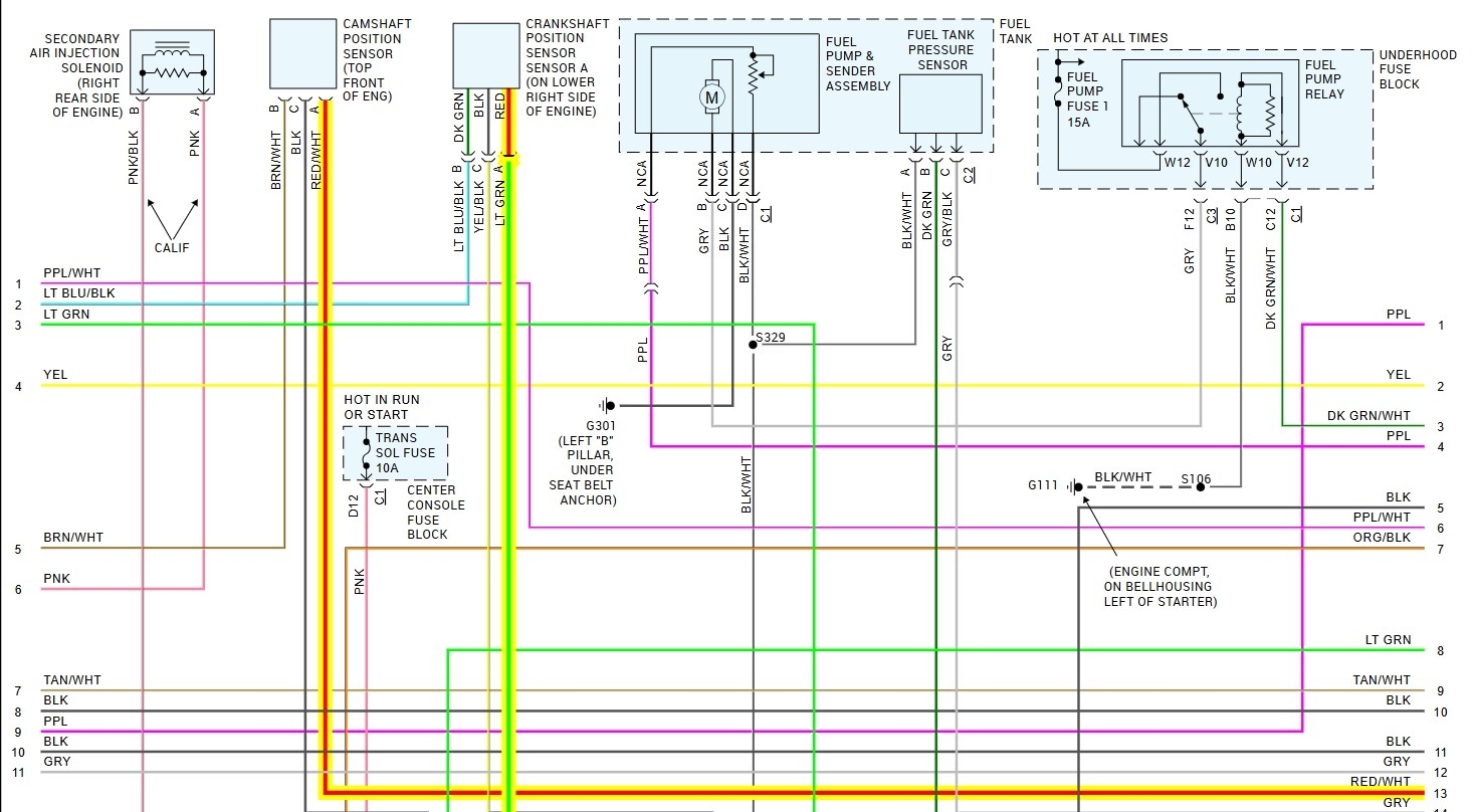
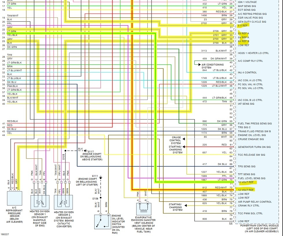
Next you need to determine why it's down, the PCM can go down if a 5volt reference is being shorted out in a sensor being pulled to ground, Any 3 wire sensor is going to use a 5volt ref, such as a throttle position sensor, MAP sensor, engine coolant temp sensor (2 wire) but should have 5v unplugged. It could also be losing power due to a bad ground or power.

I know this is a lot to take in, so if you have access to a capable scan tool that can scan other modules besides just the PCM (global OBD2). Then you could see which module is offline during the fault.
Was this
answer
helpful?
Yes
No
Saturday, June 1st, 2024 AT 2:31 PM
Tiny
REDBONE
  • MEMBER
  • 96 POSTS
Thanks for the info, I will connect scan tool to see if I can find which module is having a fit, again thank you.
Was this
answer
helpful?
Yes
No
Saturday, June 1st, 2024 AT 3:36 PM
Tiny
AL514
  • MECHANIC
  • 4,449 POSTS
Okay, if you happen to have no comms at all with the scan tool, pin 2 of the data link connector is the network wire for all the modules including the scan tool on this design, pins 4 and 5 are grounds. So, you could check pin 2 for a short to ground (0volts) or a short to power, but that's only if the scan tool doesn't work at all during the fault. Then you could try de-pining the Dark Green wire to the PCM and see if it restores communications to other modules.
Because a sensor shorting out the 5volt reference can be tricky, I'd go around unplugging sensors until the PCM comes back up. But module faults are a tough call all around. Hopefully you can at least isolate it to the engine computer. Then you might be looking at cam or crank sensor (diagram 4) faults they are on a 12volt Ref on this though, but it's not a battery feed its a Reference voltage from the PCM. It has a MAF (diagram 2) and MAP (diagram 3) on this engine as well, and they are both 3 wire too, but the MAF has a 12v feed, not 5. MAP uses 5v though.
Something else I just saw, was this engine uses 2 Crank sensors, one is a 3 wire so it's a hall effect sensor, but the other is a 2 wire for what looks like a separate ignition module (5th diagram). 2 wire crankshaft sensor won't use a reference voltage though. Weird design though.
I count (5) 5volt reference pins and (2) 12volt refs at the PCM. But they are probably all shared internal to the PCM from one regulator. Sorry to make it so confusing. Just stuff that can knock a PCM out.
Was this
answer
helpful?
Yes
No
Saturday, June 1st, 2024 AT 4:16 PM

Please login or register to post a reply.

Sponsored links