speedometer inoperable

1998 FORD E-SERIES VAN
52,000 MILES • 7.4L • V8 • 2WD • AUTOMATIC
Avatar
KEVIN1954
  • MEMBER
  • 15 POSTS
Speedometer inoperable getting signal from differential speed sensor to ABS module. supposed to be black/gray wire leading to PCM .i have no such color. wondering if anyone may know what color wires i need?
Mar 17, 2018 at 7:40 AM
Advertisement
Avatar
PATENTED_REPAIR_PRO
  • CERTIFIED EXPERT
  • 1,853 POSTS
There is no 7.4 engine. Is it a 7.3?
I see it actually as a gray/black wire.
If the odometer works, replace the instrument cluster.
Mar 17, 2018 at 7:59 AM
Avatar
KEVIN1954
  • MEMBER
  • 15 POSTS
yes my bad. it is Aiso a Thomas shuttle bus conversion.
Mar 17, 2018 at 8:01 AM
Advertisement
Avatar
KEVIN1954
  • MEMBER
  • 15 POSTS
that is what throwing me off that is what my diagram shows also.
Mar 17, 2018 at 8:08 AM
Avatar
KEVIN1954
  • MEMBER
  • 15 POSTS
already sent the cluster in for repair came back fully tested good to go.
Mar 17, 2018 at 8:12 AM
Avatar
PATENTED_REPAIR_PRO
  • CERTIFIED EXPERT
  • 1,853 POSTS
Are you getting a code P0500?
Mar 17, 2018 at 8:37 AM
Avatar
KEVIN1954
  • MEMBER
  • 15 POSTS
no codes at all.
Mar 17, 2018 at 8:39 AM
Avatar
PATENTED_REPAIR_PRO
  • CERTIFIED EXPERT
  • 1,853 POSTS
Pin 58 of the PCM is where the gray/black wire should be.
Mar 17, 2018 at 8:39 AM
Avatar
KEVIN1954
  • MEMBER
  • 15 POSTS
I think we are looking at the same diagram. There is no pin 58. This truck receives it speedometer from the differential sensor. The particular diagram is for the transmission sensor.
Mar 17, 2018 at 8:55 AM
Avatar
PATENTED_REPAIR_PRO
  • CERTIFIED EXPERT
  • 1,853 POSTS
It is there in that diagram, too. Lower right hand corner is pin 58 of the PCM, same gray/black wire.
Mar 17, 2018 at 9:23 AM
Avatar
KEVIN1954
  • MEMBER
  • 15 POSTS
that is what i am saying there is no gray/black wire on the ABS module or the PCM. all i have is the lg/bk and rd/pk sensor wires leading into the ABS module.
Mar 17, 2018 at 9:29 AM
Avatar
PATENTED_REPAIR_PRO
  • CERTIFIED EXPERT
  • 1,853 POSTS
Can you please give me the VIN number?
Mar 17, 2018 at 9:31 AM
Avatar
KEVIN1954
  • MEMBER
  • 15 POSTS
1fdse37f5whb73962
05/98
Mar 17, 2018 at 9:36 AM
Avatar
PATENTED_REPAIR_PRO
  • CERTIFIED EXPERT
  • 1,853 POSTS
So what color wire is at pin 58 of the PCM?
Mar 17, 2018 at 9:41 AM
Avatar
PATENTED_REPAIR_PRO
  • CERTIFIED EXPERT
  • 1,853 POSTS
Why are you looking under the rear axle speed sensor anyhow?
Those are the correct wires at that rear axle speed sensor, but it os the other sensor that I see is for the speedometer.
Mar 17, 2018 at 9:47 AM
Avatar
KEVIN1954
  • MEMBER
  • 15 POSTS
There is no number 58 only goes to 40 .only wires in that local are gray/red. Yellow/blue.
Mar 17, 2018 at 9:52 AM
Avatar
PATENTED_REPAIR_PRO
  • CERTIFIED EXPERT
  • 1,853 POSTS
Only 40 pins? I see over 100. 104 actually.
Where exactly is this PCM located?
Near the brake master cylinder?
See the pins here.
Mar 17, 2018 at 9:59 AM
Avatar
KEVIN1954
  • MEMBER
  • 15 POSTS
Left fender by master cylinder. My understanding from other techs the speedometer picks up its signal from the differential not the transmission. By the way i have a good signal to my scanner from the transmission sensor.
Mar 17, 2018 at 10:24 AM
Avatar
PATENTED_REPAIR_PRO
  • CERTIFIED EXPERT
  • 1,853 POSTS
That is not what I see from them wiring diagrams. Look at the gray/black wire to the instrument cluster, it comes from the transmission speed sensor.
Did you actually check that pin 58 of the PCM? or did you just assume there was no pin 58?
Mar 17, 2018 at 10:42 AM
Avatar
PATENTED_REPAIR_PRO
  • CERTIFIED EXPERT
  • 1,853 POSTS
I do not see the PCM on the fender. here is a diagram under the hood.
Mar 17, 2018 at 10:46 AM
Avatar
KEVIN1954
  • MEMBER
  • 15 POSTS
Why check check 58 or gray/black if it does not exist.
Mar 17, 2018 at 10:52 AM
Avatar
PATENTED_REPAIR_PRO
  • CERTIFIED EXPERT
  • 1,853 POSTS
I do see a mention of Check Rear Anti-Lock Brake System (RABS) Sensor

Turn ignition off. Disconnect RABS sensor connector. Sensor is located on rear differential assembly.
Programmable Speedometer/Odometer Module.
But that is the abs sensor not a speed sensor.
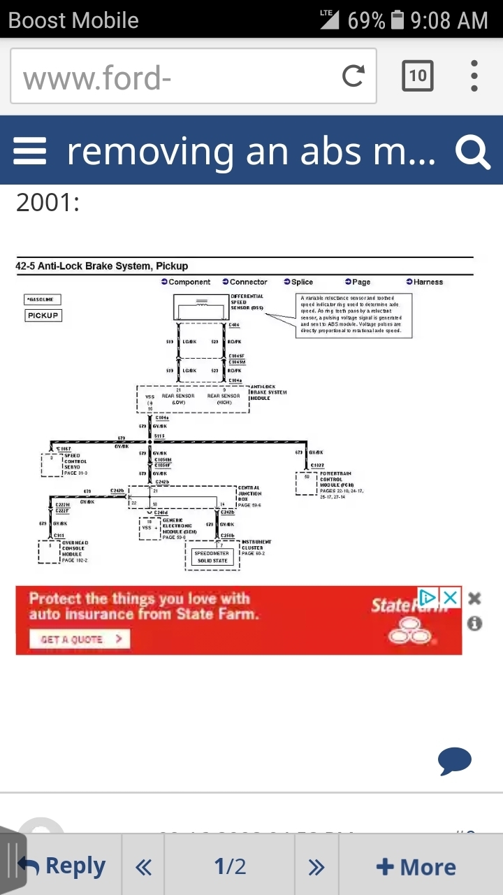
This is that entire test,

1) DTC P0500

DTC P0500 indicates PCM detected incorrect output from Vehicle Speed Sensor (VSS) sometime during vehicle operation. Possible causes for this DTC are:
PSOM output to PCM.
PSOM (+) and PSOM (-) wiring harness circuits.
Faulty PCM.
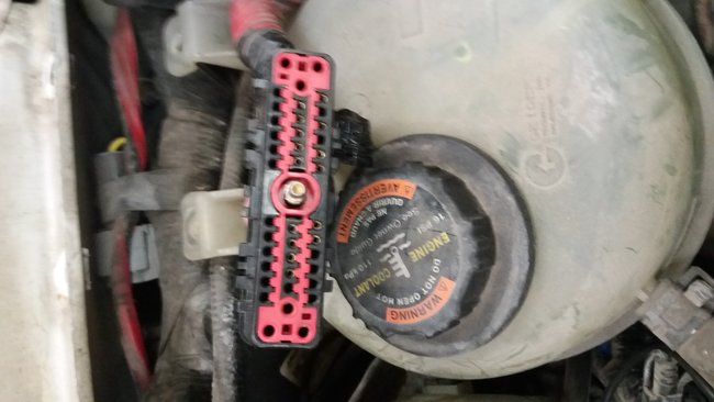
Turn ignition off. Disconnect PCM 104-pin connector and inspect for damaged pins, corrosion and loose wires. Repair as necessary. Install Breakout Box (014-00950), leaving PCM disconnected. Measure resistance between test pins No. 33 and 58 at breakout box. If resistance is 21, 000-55, 000 ohms, go to step 4). If resistance is not 21, 000-55, 000 ohms, go to next step.

2) Check PSOM Circuit Continuity

Ensure ignition is off. Disconnect PSOM wiring harness connector. PSOM is located behind left side of instrument panel. Measure resistance between test pin No. 58 at breakout box and PSOM (+) circuit (Gray/Black wire) at PSOM wiring harness connector. Also, measure resistance between test pin No. 33 at breakout box and PSOM (-) circuit (Pink/Orange wire) at PSOM wiring harness connector. If any reading is 5 ohms or more, locate and repair open circuit. Clear DTCs and repeat QUICK TEST . If both readings are less than 5 ohms or less, go to next step.
3) Check For Short Circuit

Ensure ignition is off. Measure resistance between test pin No. 58 and test pins No. 33, 51 and 71 at breakout box. If any reading is 10, 000 ohms or less, repair short circuit. Clear DTCs and repeat QUICK TEST . If all readings are more than 10, 000 ohms, go to next step.
4) Check Rear Anti-Lock Brake System (RABS) Sensor

Turn ignition off. Disconnect RABS sensor connector. Sensor is located on rear differential assembly. Measure resistance between sensor terminals. If resistance is not 1300-1550 ohms, replace RABS sensor. Clear DTCs and repeat QUICK TEST . If resistance is 1300-1550 ohms, go to next step.
NOTE: When road testing vehicle in the following step, use an assistant to record data.
5) Check PSOM Output Voltage

Turn ignition off. Connect PCM to breakout box. Connect wiring harness connector to PSOM. Set New Generation Star (NGS) scan tool for frequency measurement with a 4-volt DC scale. Connect NGS scan tool probes between test pins No. 33 and 58 at breakout box. Road test vehicle at 40 MPH or 60 MPH. Frequency should by 88-92 Hz at 40 MPH or 128-132 at 60 MPH. If frequency is as specified, replace PCM. Clear DTCs and repeat QUICK TEST . If frequency is not as specified, no fault is indicated at this time. Check for faulty instrument cluster, cruise control system or RABS.
Mar 17, 2018 at 10:53 AM
Avatar
PATENTED_REPAIR_PRO
  • CERTIFIED EXPERT
  • 1,853 POSTS
I do not know why your PCM has no pins higher than 40.
Mar 17, 2018 at 10:56 AM
Avatar
KEVIN1954
  • MEMBER
  • 15 POSTS
It is a diesel. Plus it has not got a psom. For some reason i think being a conversion is the problem.
Mar 17, 2018 at 11:26 AM
Avatar
PATENTED_REPAIR_PRO
  • CERTIFIED EXPERT
  • 1,853 POSTS
What is that you are showing me a photo of?
I am heading out, will be back later.
Are you sure you are looking at the PCM? Perhaps get the numbers off the PCM to see it is in fact the PCM.
Mar 17, 2018 at 11:29 AM
Avatar
KEVIN1954
  • MEMBER
  • 15 POSTS
Picture of the so called PCM connector. Check back later thanks for your input. Have a nice weekend.
Mar 17, 2018 at 11:40 AM
Avatar
PATENTED_REPAIR_PRO
  • CERTIFIED EXPERT
  • 1,853 POSTS
I am back, can you back the camera up and take a photo of the PCM and another photo showing where that PCM is located under the hood, because I do not see it on the fender and I do not know why they would move it when doing a conversion.
How about the part number off that PCM too?
These are the PCM part numbers I see, for federal F8UZ12A650AFH and for California F8UZ12A650AGH.
Mar 17, 2018 at 2:17 PM