Sorry for delayed reply and thank you for providing torque specs.
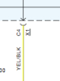
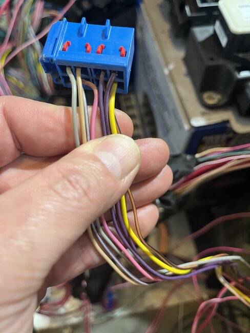
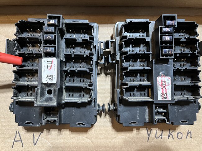
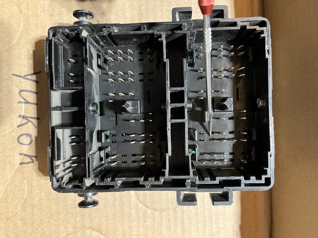
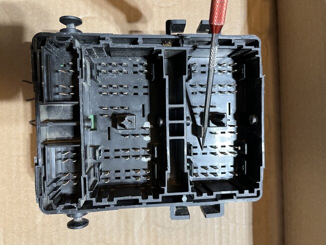
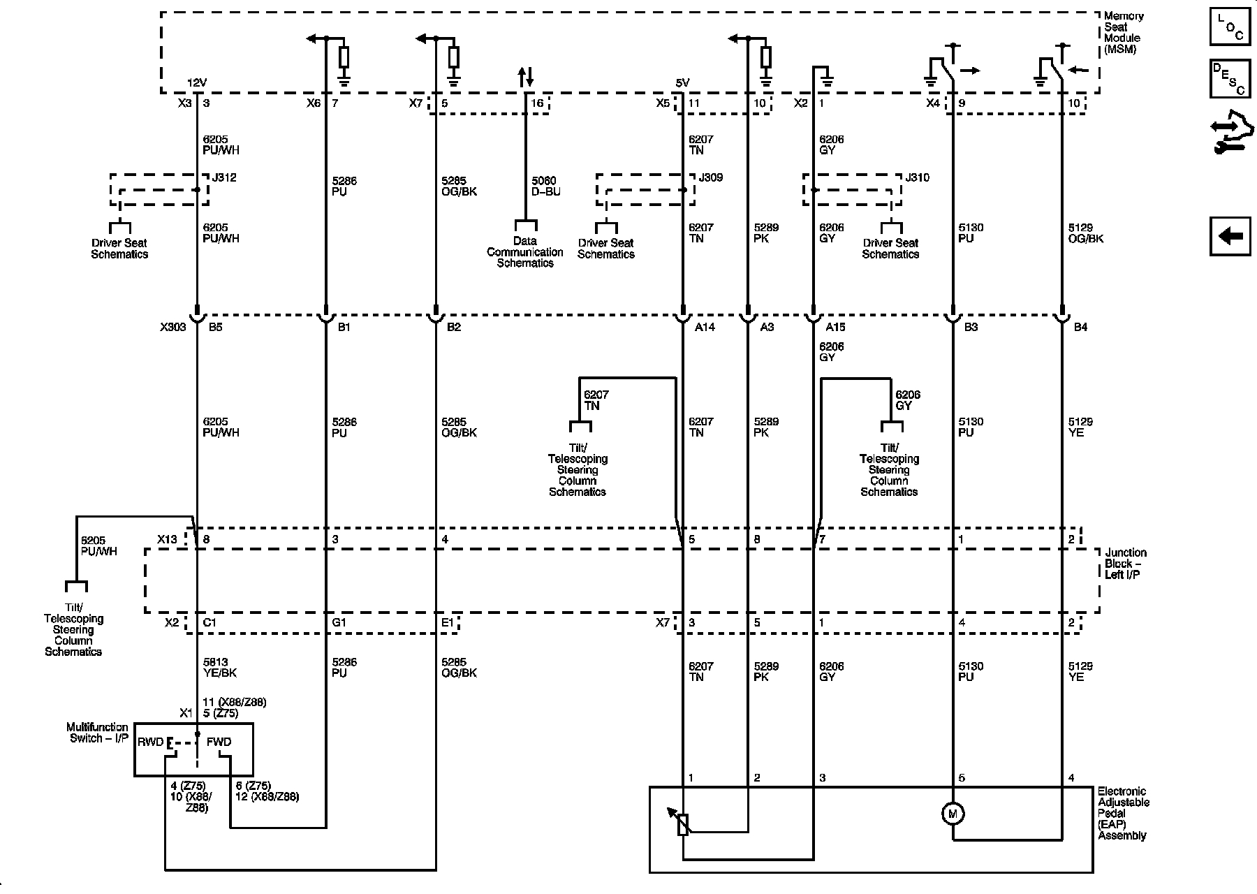
The common error I keep finding in all diagrams is - pin C4 connector X1 should be X2 pin C1. On both X1 and X2 the pin C4 is not used at all, it is not on Junction block at all. I am adding images of both Junction blocks and blue connector I was talking about in earlier messages. The image with red maker show X13 connector that only had pin 8. And the other images show that C4 pin is absent in X1 and X2 connectors on Junction block.
Now to the good news...
After completing all hardware changes (I will list all parts that were exchanged later in post), I did not need to do any programming. I am surprised and happy that I do not have to spend more money for programming. Lots of people would not believe it and in my situation it just worked. I am not original Avalanche owner, and before making any changes to my truck I did not have memory seat (AN3) and power folding mirrors (DL3) option on driver display. And the seats do get warm when lights on the door switches are on.
The details of what what removed/added.
Donors
2011 LTZ
heated seats (the exact model is not known) and module under driver seat is identical to 2010 Yukon and the long story short for short durations I had Yukon driver seat installed and everything worked.
2010 Yukon
-inside door handles with seat warmers buttons and memory buttons
-door un/lock and windows control and mirror buttons
-seats wiring harness (take all the wiring harness you can from donor, do not cut anything at yet)
-Junction Block Left I/P
-folding mirrors with turning signal (DL3)
-Brake and Accelerator Pedal Adjuster Position Sensor (potentiometer). This part is need to complete AN3 break pedal position circuit. Note white wire in pig tail from motor to adjuster position sensor goes into position #1 on motor connector.
Recipient
2013 Avalanche LT
-manual pedal position option (JF4)
-cloth non heated seat
-outside mirrors (DL8)
-rear view camera (UVC)
I made sure that both the 2010 Yukon and my 2013 Avalanche LT have the same module in the center of the cab floor, PN 13579116. The module with two yellow connectors and make sure there are air bags on both donor and seats.
The obvious steps, unbolt seats, disconnect battery and make sure air bags are deactivated before disconnecting seats. I removed all seats and carpet because my plan was to change entire seat harness and do as little of wire cutting and splicing as possible. I was lucky and on my truck wires were taped with cloth tape so I carefully untapped wires that I was going to replace.
One by one transfer wires from donor harness to recipient harness. By transfer I mean de-pin wire from connector and transfer to recipient, using terminal removal tool. I started from passenger side because it was the longest wire runs that needed most of the routing. Yes, it was time consuming and tedious process try to not tangle wires, and if you do can always reroute them by removing from connector and reinstalling back into connector. Because modules with two yellow connectors are the same the pins on yellow connectors mapped with no issues, i.e. seat belt, seat position and passenger present wires. I did read that I would have to transfer passenger present sensor and in my case I did not have to do that, the sensor from donor seat just worked. Green wires (GMLAN) get connected to GMLAN junction box in piler behind driver seat. Grounds connect to pillars on both sides. The odd thing was I had to cut big ground wire from Avalanche passenger seat because it was just spliced in in wiring harness, the donor wiring harness had dedicated ground wire, which I used and routed to pillar behind passenger seat.
The only two connectors that I had to splice were X12 pin 7 because I have UVC back up camera and adding seat harness added KB6 option (part of circuit 239). Later I realized I did not really need it because circuit 239 goes to X305 pin A4 and is not used on seat side of connector.
The other one is fuse 25 circuit 1140 in fuse block on driver side connector X2 B7. Fuse 25 is remote entry module and driver seat module power which goes to driver seat connector X303 pin B6. That is the recommendation to active module provided at www.oemcarandtruckseats.com/blogs/knowledge-base/92612615-2007-2014-nnbs-chevy-gm-seat-swap-memory-bypass-heat-setup .
I added Brake and Accelerator Pedal Adjuster Position Sensor to complete circuit for X7 pins 1,3,5 (see BlueX13Connecor picture).
Replaced mirrors, Junction Left block. I did not blindly replace Junction block, I compared circuits and reviewed the differences to make sure all connections work. The main addition was extra pins for X13 connector for power pedal control (i.e. adding AN3 option).
Before connecting seats, I also wanted to confirm that wires on new connectors would work. While doing that I came to conclusion that adding seat harness from Yukon added KB6 option even, so Yukon did not have KB6 option listed in RPO codes, which is overkill for just heated seats. KB6 option as I understand it - is both cooled and heated seats. Why/how I came to that conclusion - the wire colors on body and seat sides of connectors should match and they did not. For instance, for X303 connector (driver seat) A1 pin on body side is OG (Driver Cooled Back Signal Low (KB6)) and on seat side is L-BU (Passenger Heated Seat Back Element Control (without KB6)). But the other option for body side would match the function from seat side of connector, the other option on the body side for X303 pin A1 is (Passenger Heated Seat Back Element Control (without KB6)). And that pattern continue on all pins. So the wire color did not match but function of connection did. The only exceptions to that pattern - X303 A8 D-BU (body) and PK (seat) and X305 B5 L-BU (body) and PK (seat), both of those connections function is (Low Reference). In addition there are some wires on body side of connectors that are not used on seat side of connector. That makes me think that my truck now have wiring for cooled and heated seats, and if and when I run into set of those seats I would have to replace seats and door control switches and cooled seats should work.
Images (Click to enlarge)
Aug 18, 2026 at 5:01 PM