Here are the diagnostic procedures as outlined in the manual.
DTC P1251-P1253: THROTTLE MOTOR FULL PULSE-WIDTH MODULATION MALFUNCTION
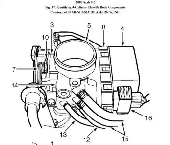
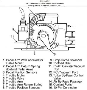
1 . Turn ignition off. Wait 10 seconds, then open and close throttle by hand. See Fig. 17. Ensure that throttle is not obstructed and that throttle spring returns throttle valve completely until contacting stop screw. If throttle valve operation is as specified, go to next step. If throttle valve operation is not as specified, repair or replace throttle body as necessary. THROTTLE BODY under FUEL SYSTEM in REMOVAL, OVERHAUL & INSTALLATION article. Go to step 3.
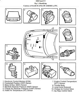
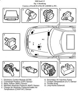
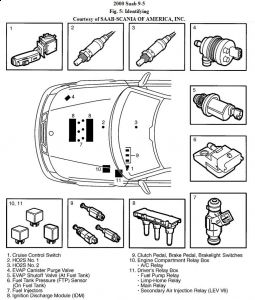
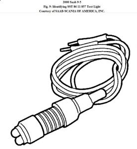
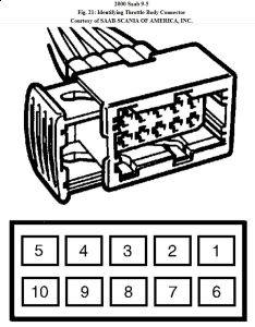
2 . Disconnect throttle body electrical connector. Connect SST 86 11 857 test light (see Fig. 9) or equivalent to throttle body harness connector terminals No. 5 (Grey/Red wire) and 10 (Blue/Red wire). See Fig. 21. Connect TECH 2 scan tool to Data Link Connector (DLC). Turn ignition on. Select ACTIVATE: THROTTLE MOTOR PWM test. The test light should alternate between green and red. If test light does not operate as specified, check for faulty circuit between throttle body harness connector terminal No. 5 and ECM harness connector terminal No. 48 (Grey/Red wire). See Fig. 1, Fig. 3 or Fig. 5 for ECM location. See Fig. 11 for ECM terminal identification. Check for faulty circuit between throttle body harness connector terminal No. 10 and ECM harness connector terminal No. 24 (Blue/Red wire). See appropriate wiring diagram in WIRING DIAGRAMS article. Repair as necessary. If test light does operate as specified, replace throttle body. Go to next step.
NOTE: Limp-home mechanism must be reset after all DTCs have been erased, otherwise limp-home solenoid will be activated.
NOTE: If sent to this procedure from DTC P0506, go to step 4.
3 . Turn ignition on. Use scan tool to clear Trionic T7 Engine Management System DTCs. Turn ignition off. Wait 10 seconds. Reset limp-home mechanism. See RESETTING LIMP-HOME SOLENOID under TESTING & REPAIR PROCEDURE. Use scan tool to clear all system DTCs. Drive vehicle for 5 minutes under varying loads and engine RPM. Recheck for any stored DTCs. If DTC P1251 is present, substitute known good ECM and retest system. See ENGINE CONTROL MODULE (ECM) under COMPUTERIZED ENGINE CONTROLS in REMOVAL, OVERHAUL & INSTALLATION article.
4 . Start engine and allow it to run until radiator fan turns on. Turn A/C, rear window defroster and headlights on to create load on engine. Use scan tool to select READ VALUE: CHARGE AIR CONTROL VALVE. If scan tool display reads Max +/- 50 RPM, clear DTCs. If display reads other than specified, problem is still present. Restart diagnostic procedure.

Sunday, November 8th, 2009 AT 1:39 AM


