See if this helps.
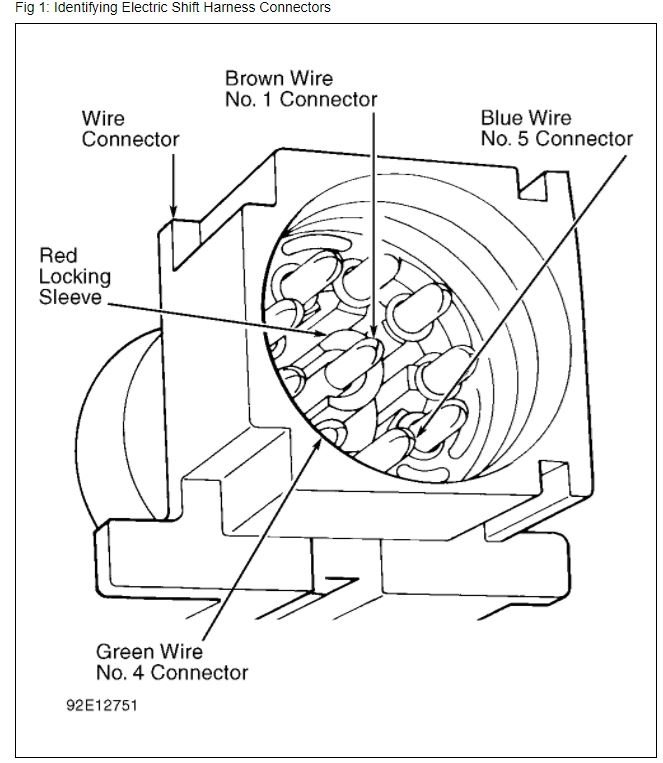
On electronic shift models remove speed sensor bracket. Fabricate tool by forming small hook at tip of paper clip or safety pin. Remove Red locking sleeve from connector by hooking with tool and pulling from bottom.
Fig 1: Identifying Electric Shift Harness Connectors
G92E12751
Courtesy of FORD MOTOR CO.
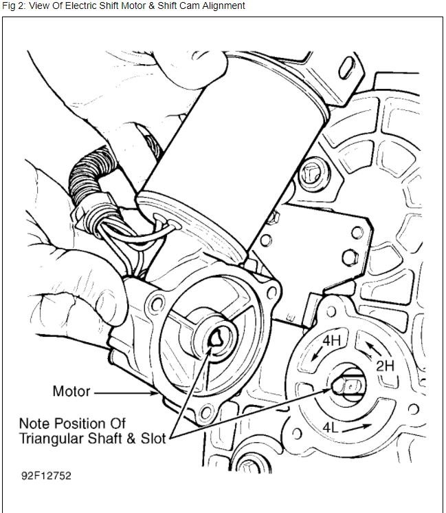
Remove Brown wire (center), Green (No. 4) wire and Blue (No. 5) wire by pulling from back of connector. See Fig 1. Remove speed sensor and shift motor, noting position of triangular shaft in case and slot in motor. See Fig 2.
On all models remove case-to-cover bolts and pry front case and rear cover apart. Ensure rear cover is facing up. If speedometer drive gear or ball bearing assembly is to be replaced, remove rear output shaft oil seal. Remove internal snap ring and drive bearing assembly from outside case.
If required, remove front output shaft caged needle bearings from rear cover. Remove clutch coil assembly, "O" rings and Brown wire from cover of electronic shift model. Remove 2WD-4WD shift fork return spring. Remove lock-up hub from output shaft. See Fig 3.
Fig 2: View Of Electric Shift Motor & Shift Cam Alignment
G92F12752
Images (Click to make bigger)
SPONSORED LINKS
Sunday, April 22nd, 2018 AT 8:14 AM


