Hi,
That's a good question simply because I never paid attention. I always mark one side to reinstall.
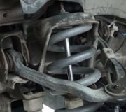
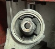
I looked up the directions for removal and replacement. It doesn't indicates a specific direction, so I am going to say it should work either way. Here are the directions. I don't know if you have a FWD or AWD model, but it shows both. The attached pics correlate with the directions.
__________________________________________________________________________
2010 Ford Fusion FWD L4-2.5L
Upper Arm
Vehicle Steering and Suspension Suspension Control Arm Service and Repair Removal and Replacement Rear Suspension Upper Arm
UPPER ARM
204-02 Rear Suspension 2010 Fusion, Milan, MKZ, Fusion Hybrid, Milan Hybrid
REMOVAL AND INSTALLATION
Upper Arm
Front Wheel Drive (FWD) Vehicles
See pic 1
Item Part Number Description
1 5500 Upper arm
2 W712769 Upper arm inboard bolt
3 W500546 Upper arm outboard bolt
4 W704586 Shock absorber lower bolt
5 W302116 Shock absorber lower flagnut
All-Wheel Drive (AWD) Vehicles
See pic 2
Item Part Number Description
1 W520215 Upper arm inboard nut
2 W712769 Upper arm inboard bolt
3 5500 Upper arm
4 W500547 Upper arm outboard bolt
5 W520215 Upper arm outboard nut
6 W712880 Shock absorber lower bolt
7 18080 Shock absorber
8 � Shock absorber lower mount bushing
9 W302116 Shock absorber lower flagnut
Removal and Installation
NOTICE: Suspension fasteners are critical parts because they affect performance of vital components and systems and their failure may result in major service expense. New parts must be installed with the same part numbers or equivalent part, if replacement is necessary. Do not use a replacement part of lesser quality or substitute design. Torque values must be used as specified during reassembly to make sure of correct retention of these parts.
All vehicles
Remove the wheel and tire. For additional information, refer to Section 204-04.
Using a suitable jack, support the trailing arm.
NOTICE: Do not fully tighten the shock absorber lower nut until the suspension is at the bushing fastener tightening position. This will prevent incorrect clamp load and bushing damage.
Remove and discard the shock absorber lower bolt and flagnut.
To install, tighten the new bolt and flagnut to 90 Nm (66 lb-ft), All-Wheel Drive (AWD) vehicles.
To install, tighten the new bolt and flagnut to 115 Nm (85 lb-ft), Front Wheel Drive (FWD) vehicles.
Front Wheel Drive (FWD) vehicles
Remove and discard the upper arm outboard bolt.
To install, tighten the new bolt to 110 Nm (81 lb-ft) with the suspension at the bushing fastener tightening position.
All-Wheel Drive (AWD) vehicles
Remove and discard the upper arm outboard bolt and nut.
To install, tighten the new nut and bolt to 110 Nm (81 lb-ft) with the suspension at the bushing fastener tightening position.
All vehicles
Carefully lower the trailing arm and remove the jack.
NOTE: Position the shock absorber as necessary to remove the upper arm.
NOTE: When tightening the upper arm inboard bolt, the suspension must be at the bushing fastener tightening position.
Remove and discard the upper arm inboard bolt and remove the upper arm.
To install, tighten the new bolt to 100 Nm (74 lb-ft) and then rotate an additional 90 degrees.
NOTICE: Before tightening any suspension bushing fasteners, the suspension must be at the bushing fastener tightening position. Use a suitable jack to raise the suspension until the distance between the center of the hub and the lip of the fender is equal to 395 mm (15.55 in). This will prevent incorrect clamp load and bushing damage.
To install, reverse the removal procedure.
See pic 3
Check and, if necessary, adjust the rear
camber. For additional information, refer to Section 204-00.
______________________________________
I hope this helps. Let me know if you have other questions.
Take care,
Joe
Images (Click to make bigger)
Sunday, July 26th, 2020 AT 1:39 PM


