You don't know how refreshing it is to have someone who uses a scope. Thats really great, so you're saying the 5v Ref for some sensors is now only 3volts? Or what reference voltage are you referring to?
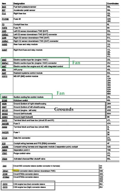
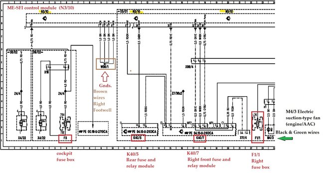
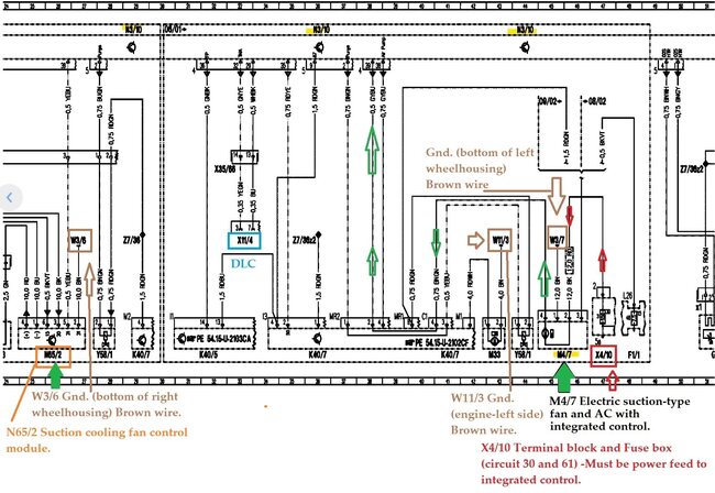
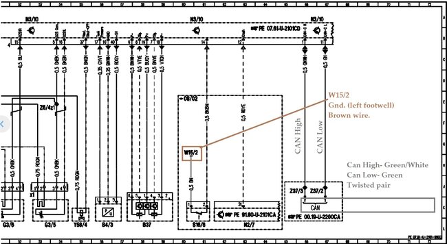
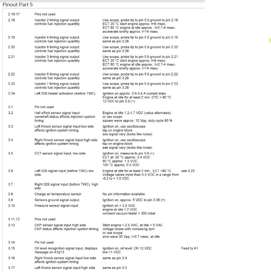
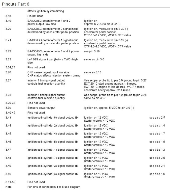
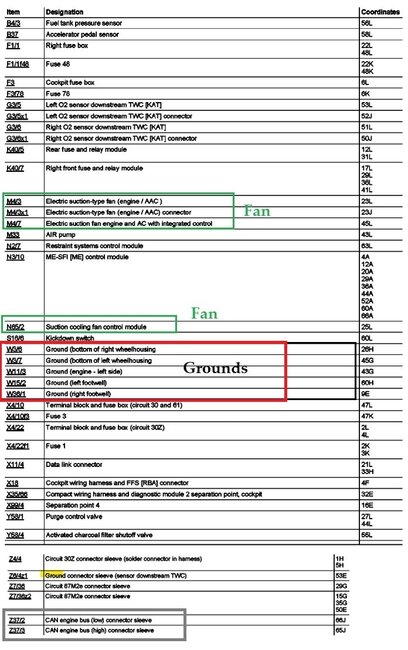
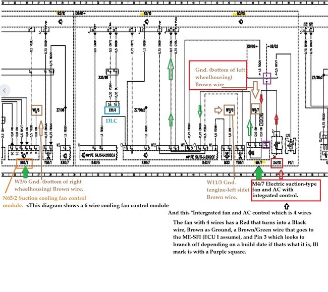
Sorry about the ground locations, they were on this list, but difficult to see,
These are the grounds for the ECU diagrams section that listed the fan as well.
If a bad sensor is affecting the 5volt Ref, and that ref is shared with other sensors internal to the ECU, it can cause strange symptoms, usually a sensor shorts out and just pulls the 5vRef to ground, which can cause the ECU to completely shut down.
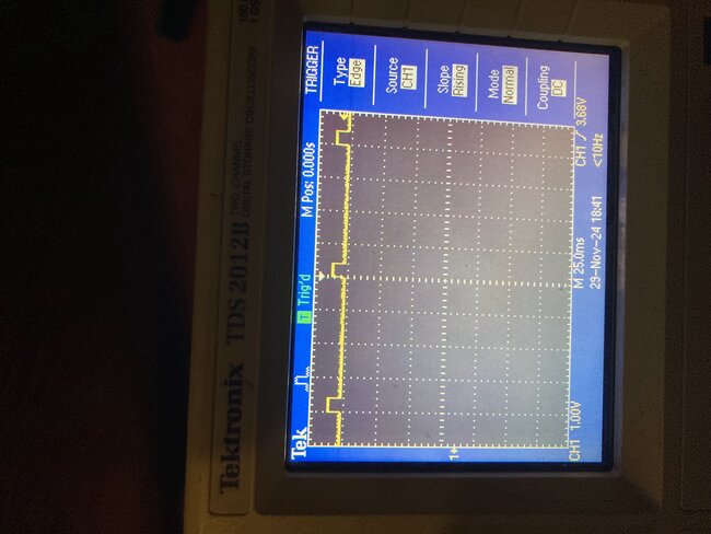
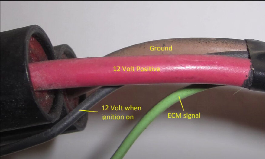
So, your scope is set to 1v/div, so the signal is riding on 5volts, with these small jumps of 0.8v every 100ms, and this is happening on the red wire?
The grounds listed below are all Brown wires, just fyi.
Check some other 3 wire sensors on the engine to see if anything else has a low reference voltage, being at 3volts is very strange, that almost makes me think there might be something wrong with the voltage regulator, then again you said the vehicle runs fine, I'm going to message a tech that works on Euro vehicles all the time and see what he thinks about the fan, the problem is these wiring diagrams are terrible,
You scope waveform looks like that wire is possibly shorted to a 5volt wire or a bad ground can cause elevated voltage.
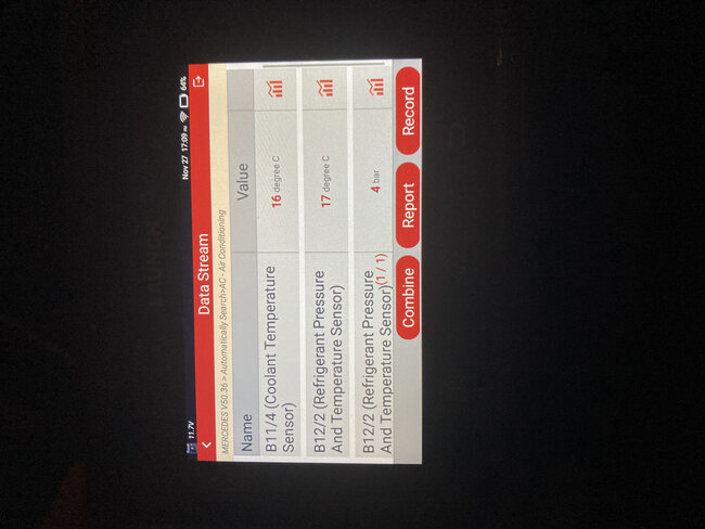
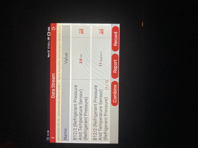
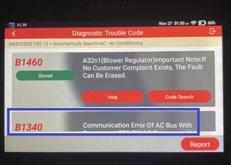
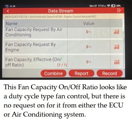
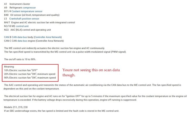
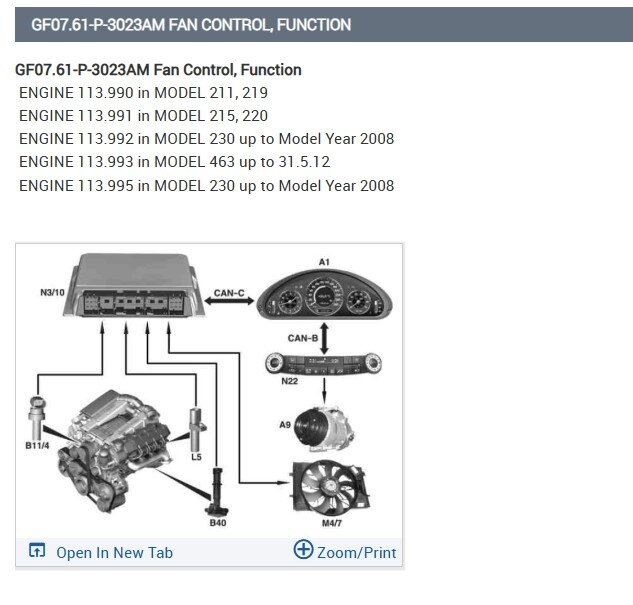
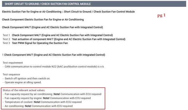
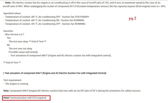
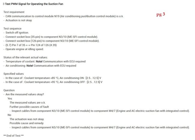
I did find this small flow chart for the "Suction Fan Control Module- Short to Ground" (diagrams 3-5), and then there is also a section for short to power, but its the same exact flow chart. It does say that communication is required which you have a code for. But service info lists every code as being a "P" code and not B, I don't know if that's something to do with that specific scan tool communications or not.
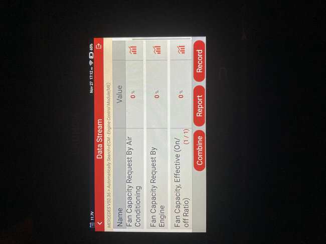
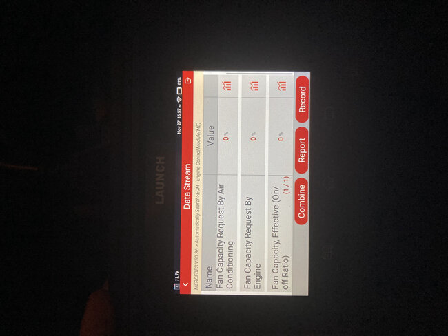
Part of the flow chart on pages 2&3 mention an Actuation test of the Fan, which is going to be a bi-directional control, and probably monitor the Fan speed data PID while doing so,
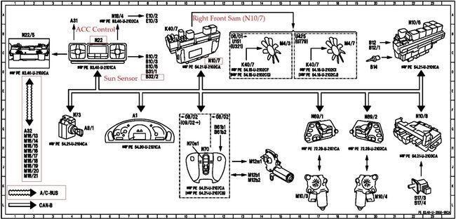
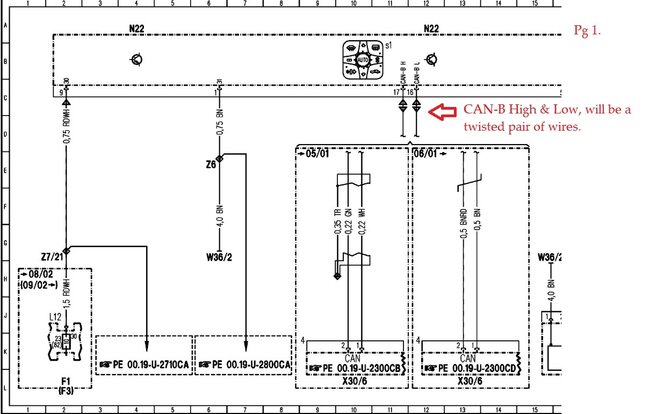
Diagram 6 shows a list of the different Can networks in the vehicle.
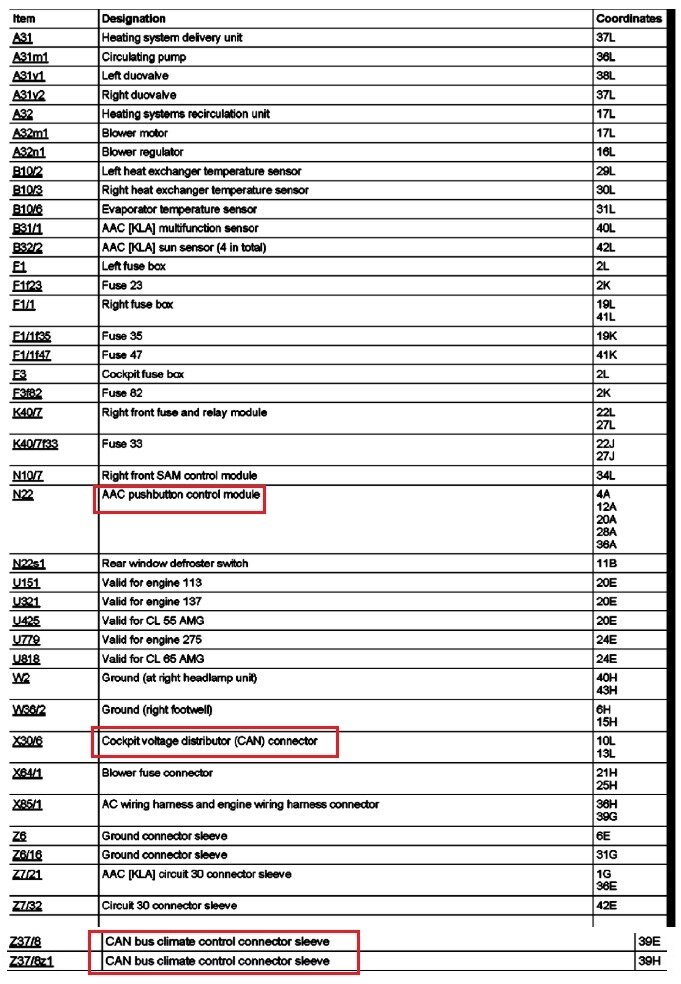
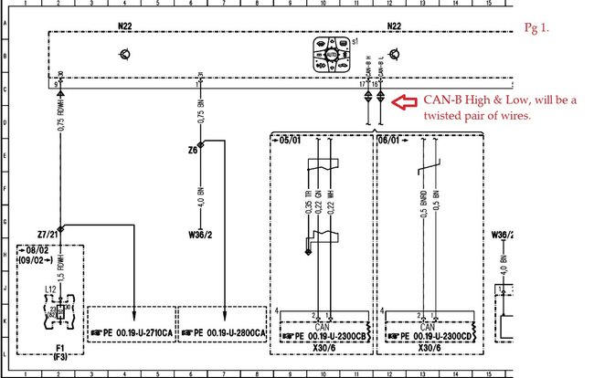
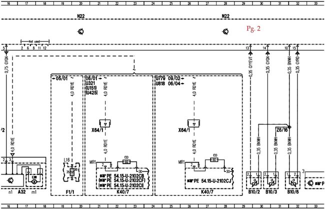
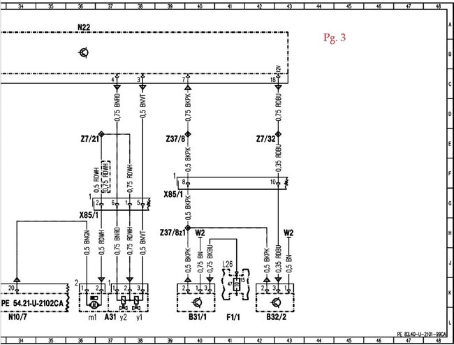
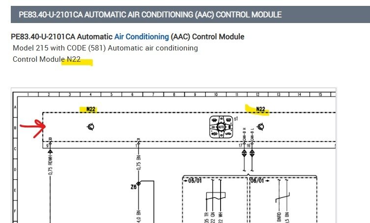
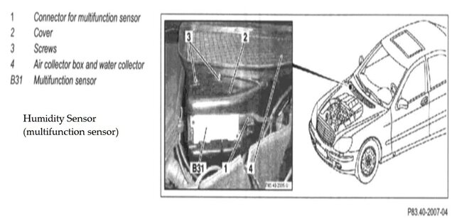
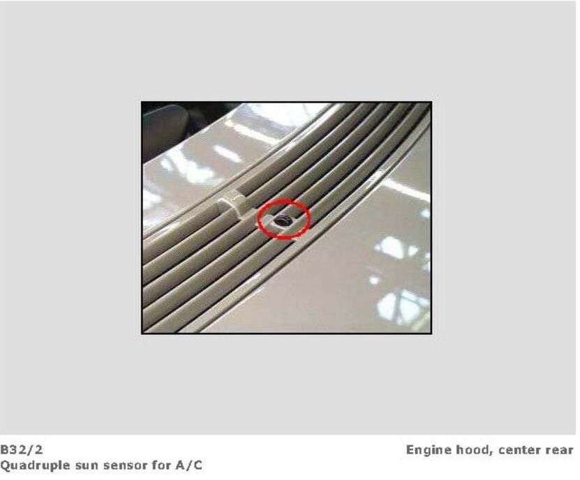
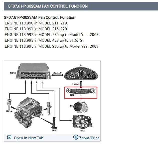
But I think the real issue is a loss of comms with the ACC pushbutton control module (N22) since the sun sensor and the humidity sensor both input to that module, and that might be why they are setting B codes, and not powertrain codes.
The ACC control module looks like the control head for the heater and AC.
Thats the main unit at the top of the HVAC wiring diagrams (#8 below) N22, very in-depth system with a ton of modules.
Images (Click to make bigger)
Friday, November 29th, 2024 AT 12:36 PM


