Hello
Thanks for the info
Is the shifter stuck in park or another gear?
So if I understand you correctly. . ...you can insert the key but cannot turn it and it is in the off position. . ...the steering wheel turns freely from side to side and the gear shift is stuck in Park and will not move?
I was wanting to verify the shifter was in Park
I am attaching the info on ignition switch lock cylinder replacement. In it talks about if you cannot rotate the key. . .. . .. . .I put those directions at the end.
It appears the locking mechanism is on the ignition switch lock cylinder.
Ignition Switch Lock Cylinder Replacement (Pontiac)
Removal Procedure
Note: In the Event it is necessary to replace the Lock cylinder housing, You will need to remove the pass lock sensor connector and the shift lock control.
To remove the pass lock connector or the shift lock control from the Lock Cylinder housing, you will first need to remove the Ignition lock cylinder.
If you try to remove the connector before removing the lock cylinder you will damage the pass lock connector.
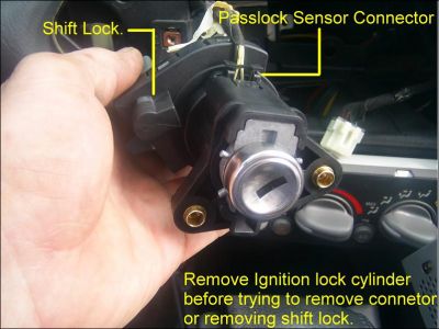
Important: Perform the BCM theft deterrent relearn procedure whenever you replace the ignition switch lock cylinder.
Disconnect negative battery cable. Refer to BATTERY NEGATIVE CABLE DISCONNECT/CONNECT PROCEDURE
1. Remove instrument panel (IP) accessory trim plate.
2. Insert the key and turn the ignition switch lock cylinder to the ON position.
3. If the cylinder does not rotate or is seized, follow the procedure in the ignition switch replacement. Refer to IGNITION SWITCH REPLACEMENT (PONTIAC) or IGNITION SWITCH REPLACEMENT (OLDSMOBILE)
4. Using a small curved tool, depress and hold the retaining tab on the ignition switch lock cylinder.
5. Using the key as an aid, pull to remove the lock cylinder from the switch.
6. Remove the key from the lock cylinder.
Installation Procedure
1. Code the ignition switch lock cylinder, if necessary.
2. Insert the key and turn the lock cylinder to the ON position.
3. Align the lock cylinder to the ignition switch, then press the cylinder into place.
4. Turn the key to the OFF position and remove the key.
5. Install the IP accessory trim plate. Refer to
6. Connect the negative battery cable. Refer to BATTERY NEGATIVE CABLE DISCONNECT/CONNECT PROCEDURE
7. If a new lock cylinder was installed, perform the BCM theft deterrent relearn procedure. Refer to BODY CONTROL MODULE (BCM) PROGRAMMING/RPO CONFIGURATION
If you cannot rotate the key. . ...
1. If the lock cylinder does not rotate or is seized, perform the following procedure:
1. 7.1. Protect the immediate work area with suitable material such as clean shop towels or a clean fender cover.
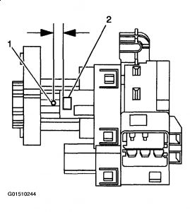
2. 7.2. Locate the surface for the ignition switch lock cylinder release button (2) on the plastic ignition switch housing and center punch a location (1) on the rib 9.5 mm (3/8 in) rearward, toward the key entry end, from the cylinder release button.
3. 7.3. Carefully drill a pilot hole through the plastic housing with an 1/8-inch drill bit.
4. 7.4. Carefully drill a larger hole at the pilot location, and slightly into the ignition switch lock cylinder surface to break the release button retaining spring using a 9/32-inch drill bit.
5. 7.5. Remove portions of the broken spring from the hole using a small suitable tool.
6. 7.6. Grasp the ignition switch lock cylinder and remove the cylinder from the switch housing.
7. 7.7. Remove any plastic flashing from the drilling operation, and using compressed air blow out the ignition switch assembly.
8. 7.8. Follow the service manual procedures when cylinder coding is required.
Fig. 62: Locating Ignition Switch Lock Cylinder Release Button
2. Press the transaxle park/lock cable retainer to release, then pull to remove the park/lock cable from the ignition switch.
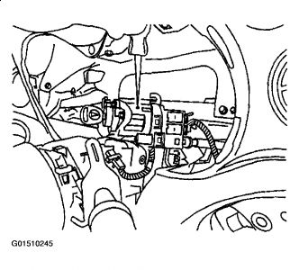
3. Remove the ignition switch lock cylinder from the ignition switch, by pressing the retaining tab and pulling the cylinder out with the key.
Fig. 63: Removing Ignition Switch Lock Cylinder From Ignition Switch
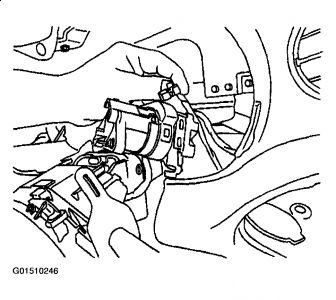
Important: Remove the ignition switch lock cylinder before you remove the Passlock electrical connector.
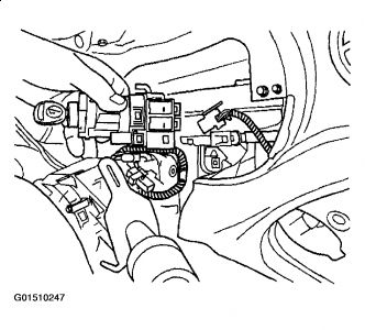
4. Disconnect the pass lock electrical connector from the ignition switch.
Fig. 64: Disconnecting Pass Lock Electrical Connector From Ignition switch
5. Disconnect the electrical connectors from the ignition switch.
6. Remove the ignition switch through the I/P cluster opening.
Fig. 65: Disconnecting Electrical Connectors From Ignition Switch
Courtesy of GENERAL MOTORS CORP.
Sunday, August 30th, 2009 AT 6:25 PM


