Disconnect the negative battery cable.
Remove the left sound insulator.
Remove the ignition switch trim ring. Pry outward with a flat-bladed tool.
Remove the accessory trim plate.
Remove the upper steering column cover. Pry outward with a flat-bladed tool.
Remove the instrument cluster trim plate.
Remove the instrument panel cluster.
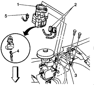
Remove the ignition switch bolts.
Disconnect the electrical connectors (4,5).
Disconnect the ignition lock cable (2) from the ignition switch (1).
Remove the ignition switch (1) from the vehicle.
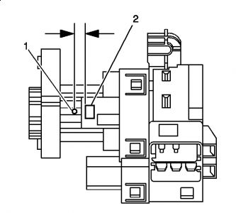
Insert the key into the ignition switch (1) cylinder. Rotate the key to the RUN position.
Press the cylinder release plunger, located at the 4 o'clock position on the ignition switch (1).
Use the key in order to pull the cylinder from the ignition switch (1).
INSTALLATION PROCEDURE
Connect the ignition lock cable to the ignition switch (4,5).
Install the ignition switch (1).
Connect the electrical connectors(2).
Install the ignition switch bolts.
Install the instrument panel cluster.
Install the instrument cluster trim plate.
Install the upper steering column cover. Ensure unit locks into place.
Install the accessory trim plate.
Install the ignition switch trim ring. Ensure unit locks into place.
Install the left sound insulator.
Connect the negative battery cable.
Reprogram the Body Control Module (BCM) .
Important: You must perform the BCM theft deterrent relearn procedure after replacement of the ignition switch Lock Cylinder. Refer to Password Learn Procedures in Body Control System. See: Computers and Control Systems Body Control Module Service and Repair.

sometimes you have to drill the ignition switch housing open to remove the cable.
Sunday, February 7th, 2010 AT 9:35 AM


