Instrument cluster consists of electronic analog gauges, various warning lights, and optional tachometer. See Fig. 1 . Vehicles equipped with tachometer have an electronic vacuum fluorescent transmission range indicator (PRND3L), odometer and trip odometer display. Vehicles without tachometer are equipped with a cable-operated transmission range indicator.
Instrument cluster is equipped with the following warning lights:
Battery voltage.
Cruise (speed control).
Door ajar.
Fasten seat belt.
Lift gate ajar.
Low fuel level.
Low windshield washer fluid level.
Traction Control.
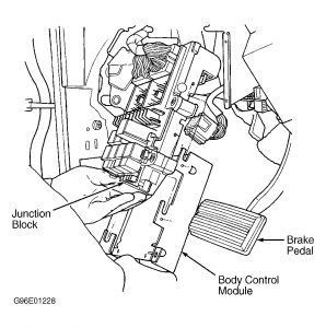
The Body Control Module (BCM), which receives input from various sensors, sends display information to instrument cluster and operates gauges. Instrument cluster incorporates a self-test diagnostic feature to identify electronic problems. BCM, Powertrain Control Module (PCM), and Transmission Control Module (TCM) are continuously monitored by the diagnostic system.
NOTE:Testing of instrument panel and gauges requires using a scan tool to check circuits connected to Body Control Module (BCM). See VEHICLE COMMUNICATIONS in BODY CONTROL COMPUTER article.
SELF-DIAGNOSTICS
With ignition off, press and hold TRIP and RESET buttons while turning ignition switch to ON position. Continue to hold TRIP and RESET buttons until odometer window displays CODE (approximately 5 seconds). If problem exists, system will display diagnostic trouble codes. See DIAGNOSTIC CODE CHART table. If no problem exists, Code 999 (end test) will be displayed.
DIAGNOSTIC CODE CHART
CodeDescription
110.......Cluster Memory Fault
111.......Cluster Calibration Fault
905.......No CCD Bus Message From TCM
921.......Odometer Fault From BCM
940.......No CCD Bus Message From PCM
After diagnostic code display ends, instrument cluster will go into each of the following tests in order:
Dim test.
Calibration test.
Odometer segment test.
Electronic Transmission Range indicator segment test.
Dim Test
CHEC-0 will be displayed in odometer window. Instrument cluster will dim Vacuum Florescent (VF) display. If VF displays do not dim, a problem in instrument cluster exists. See BODY CONTROL COMPUTER TESTS in BODY CONTROL COMPUTER article.
Calibration Test
CHEC-1 will be displayed in odometer window. Each of instrument cluster gauges will move sequentially through each calibration point. See GAUGE CALIBRATIONS table. If gauge needle is not calibrated properly, a problem in instrument cluster exists. See BODY CONTROL COMPUTER TESTS in BODY CONTROL COMPUTER article for gauge recalibration procedures.
GAUGE CALIBRATIONS
Gauge Sequence.....Calibration Point
Speedometer
1......0 MPH (0 Km/h)
2......20 MPH (40 Km/h)
3......55 MPH (80 Km/h)
4......75 MPH (120 Km/h)
Tachometer
1.....0 RPM
2.....1000 RPM
3.....3000 RPM
4.....6000 RPM
Fuel Gauge
1.....Empty
2.....1/8 Full
3......1/4 Full
4.......Full
Temperature Gauge
1......Cold
2......Low Normal
3......High Normal
4......Hot
Odometer Segment Test
CHEC-2 will be displayed in odometer window. Each segment of odometer will light sequentially. If any segment does not light, replace instrument cluster.
Electronic Transmission Range Indicator Segment Test
CHEC-3 will be displayed in odometer window. Each segment of electronic transmission range indicator will light sequentially. If any segment does not light, replace instrument cluster.

Saturday, November 22nd, 2008 AT 8:05 AM
