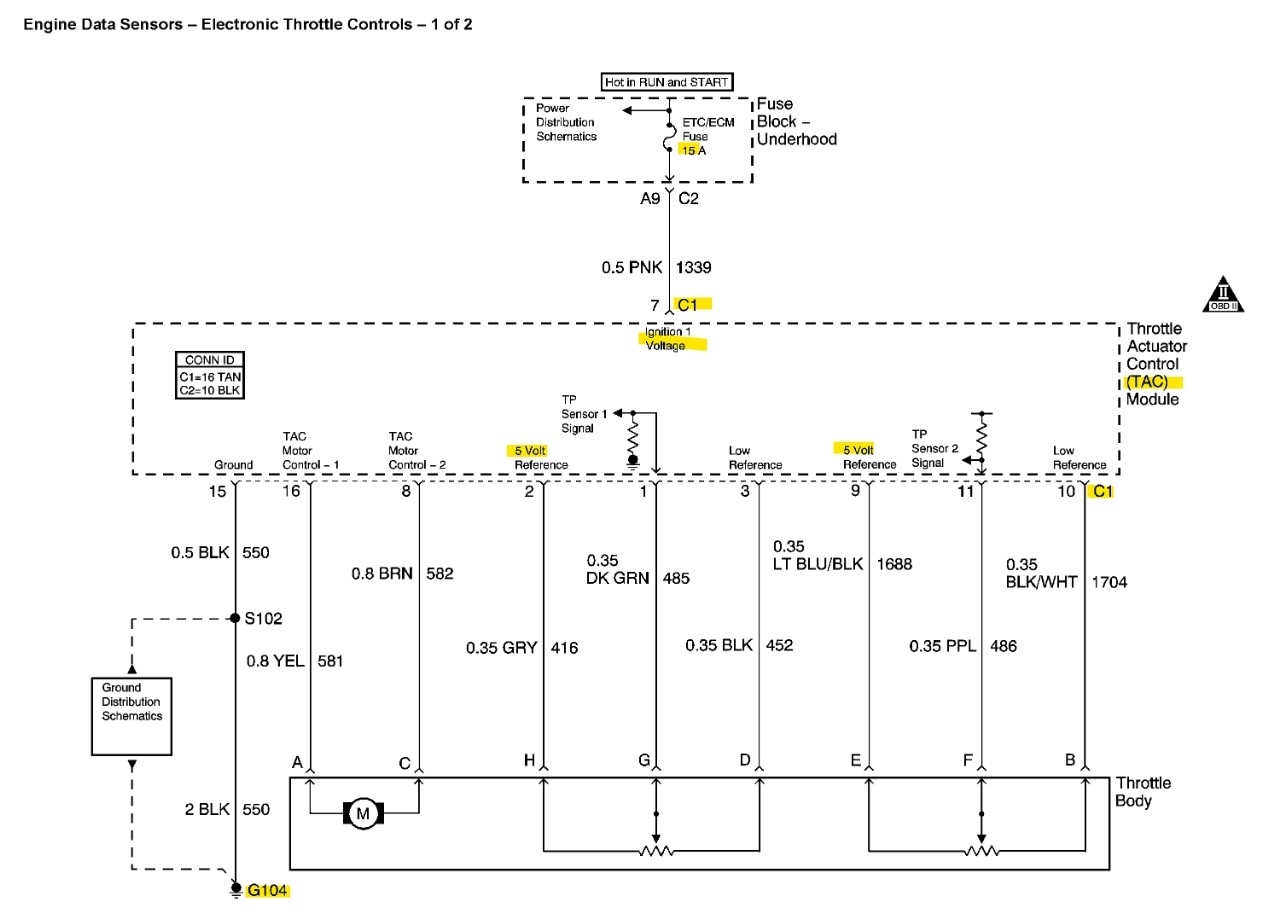
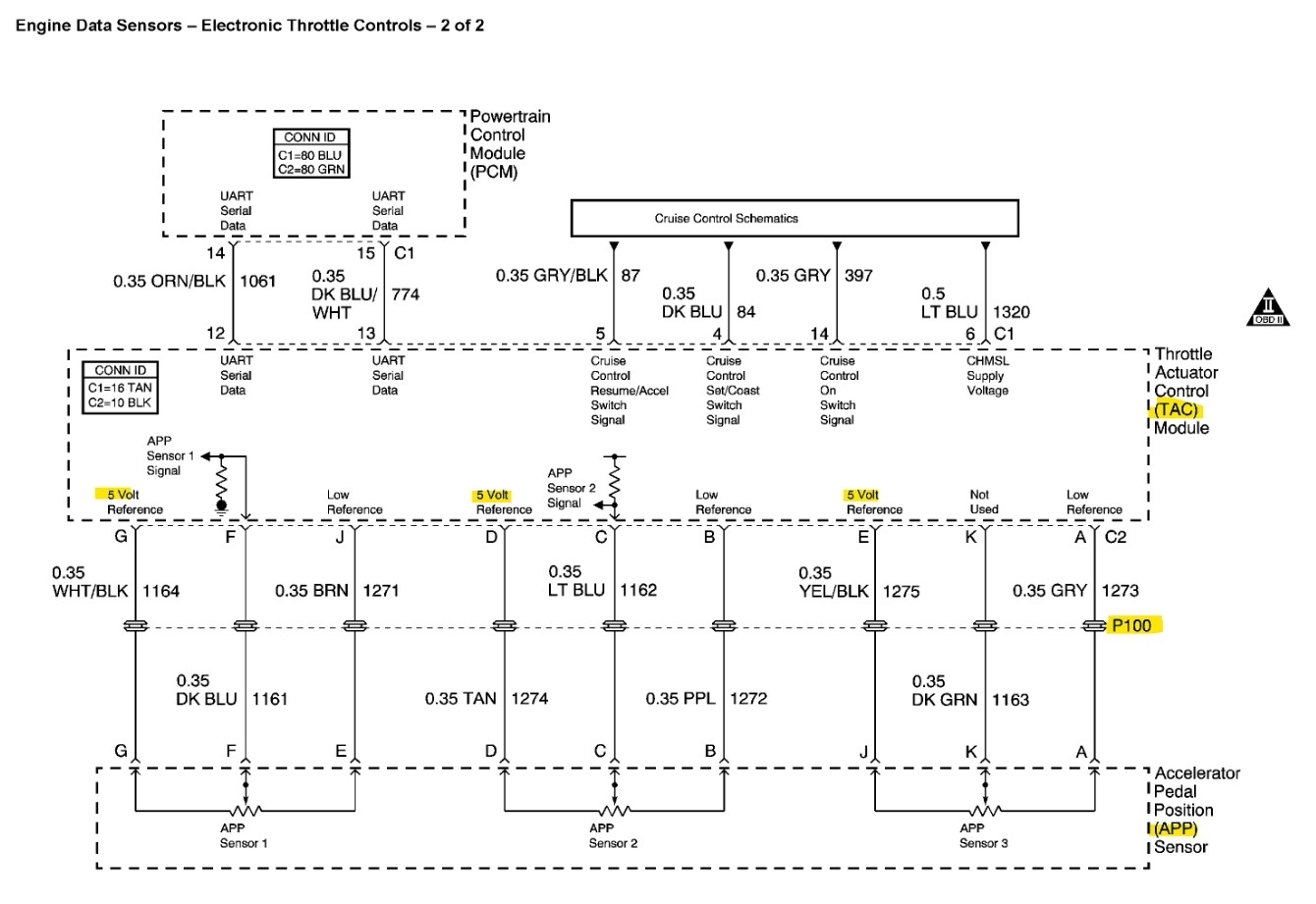
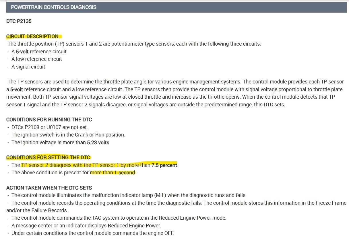
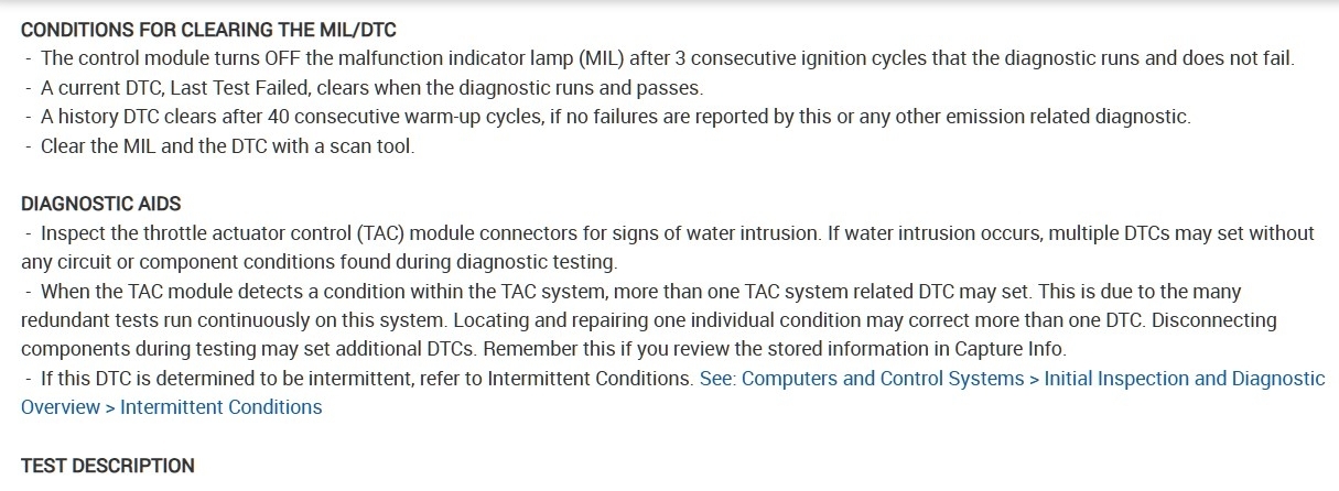
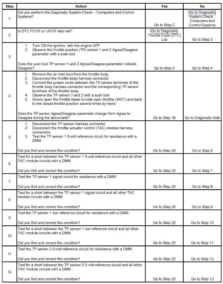
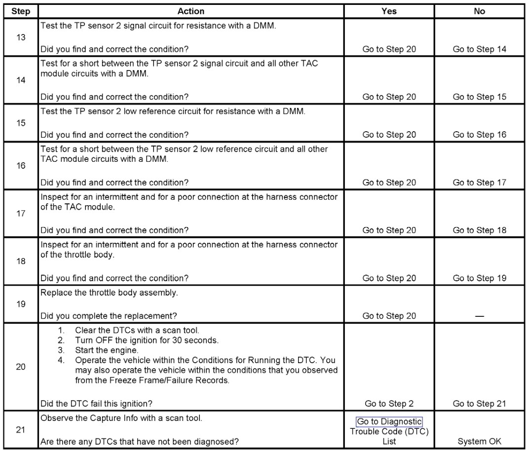
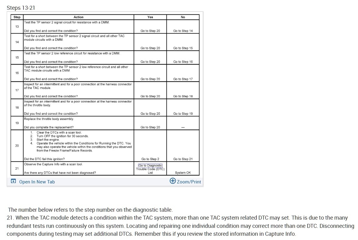
The first 2 diagrams are the oem wiring for the TAC, APP, and TPS. Along with the code setting criteria and what the ECM is seeing. The last 3 diagrams are the Flow chart for that code. You can follow it if you get down a rabbit hole, but start with checking connectors and wiring again, many times it turns out to be pin fitment or broken wire strains inside insulation, and its not always easy to find.
When wires break the copper strains inside the insulation its due to either water getting in there you can usually see that wire is discolored somewhat where its having a problem inside. It discolors because moisture got inside and rotted the wiring.
the P100 on the 2nd page below is the pass through the firewall, there will most likely be a bulk harness connector there.
The throttle body doesnt have any inline connectors with the TAC, and P100 might not even be a bulk connector, just a pass threw.
When you check the 5volt References at the sensors, I like to check them by using the body ground and then also the sensor ground just to be sure.
But let us know what you find.
Images (Click to enlarge)
Aug 5, 2026 at 3:05 PM