Good morning,
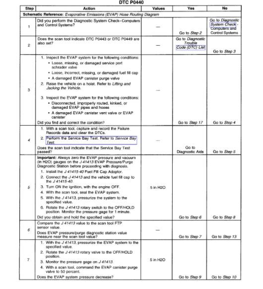
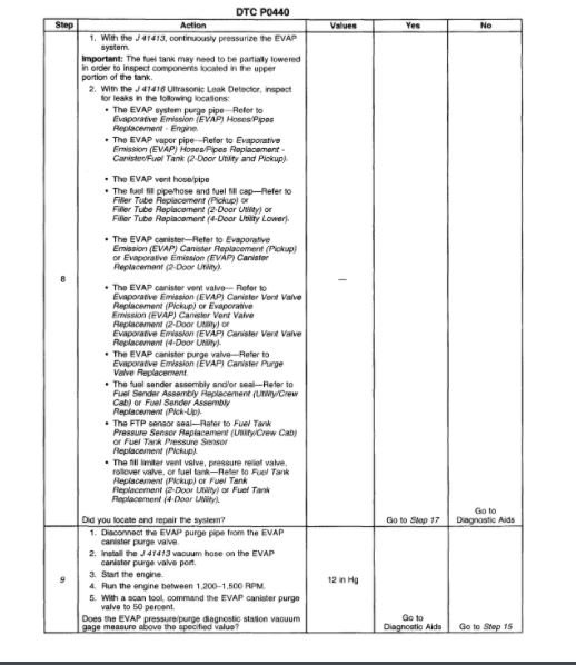
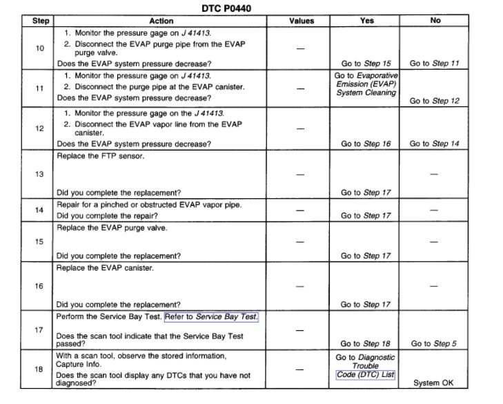
I attached the description and the flow chart for the code below.
You will need an advanced scan tool to monitor the system to be sure the controls are working.
https://www.2carpros.com/articles/how-emission-control-systems-work
A smoke test would be a good idea as well. It applies a small vacuum and monitors whether it leaks down or holds. The smoke test will show leaks from this test if it fails. If you have a scan tool, you can do a bay test where you force the ECM to do a evap test to see if it will pass.
https://www.2carpros.com/articles/evap-system-code-repair
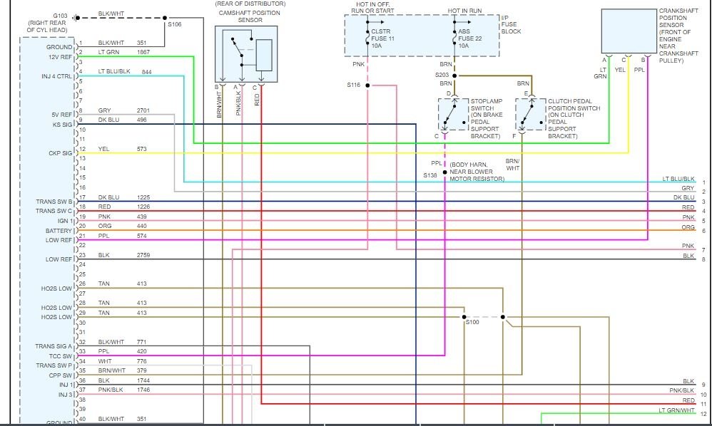
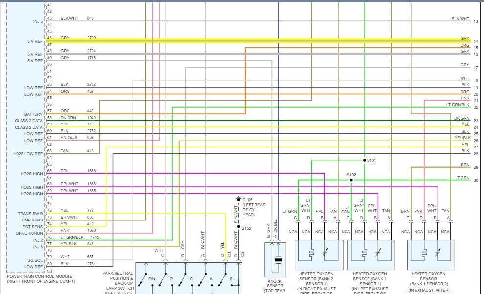
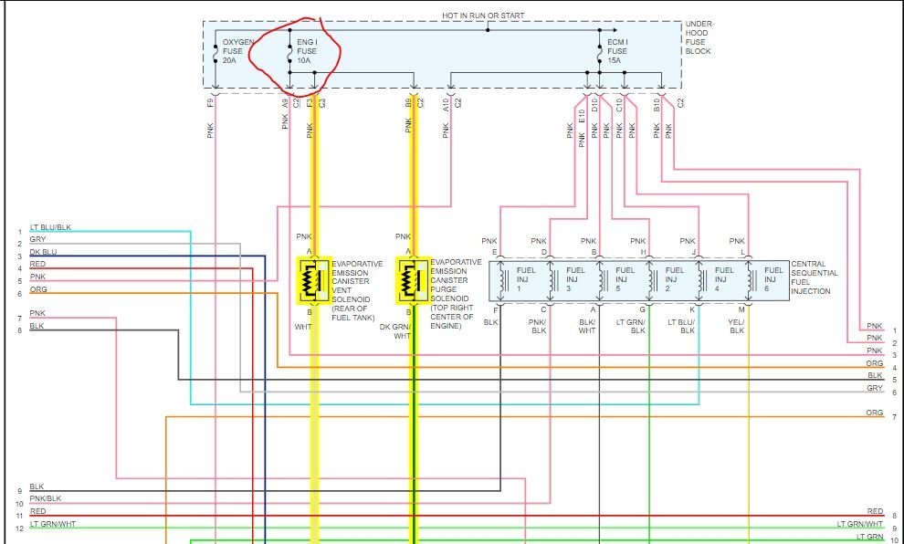
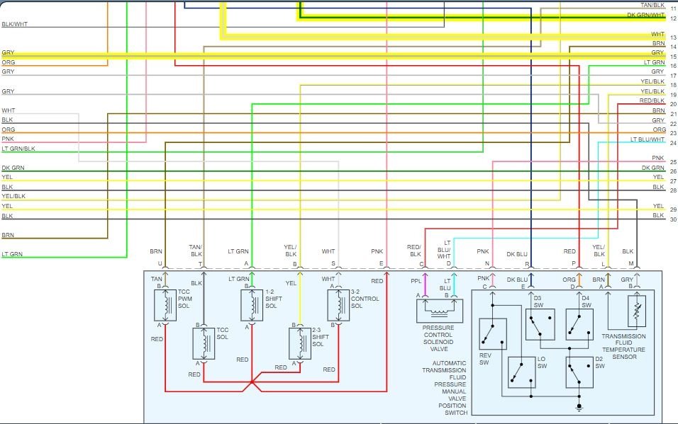
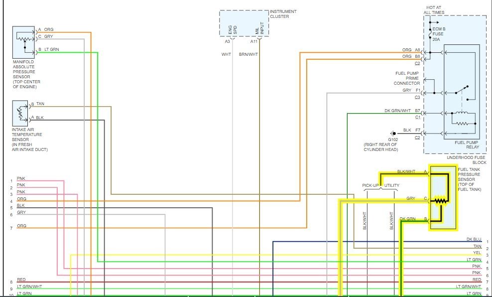
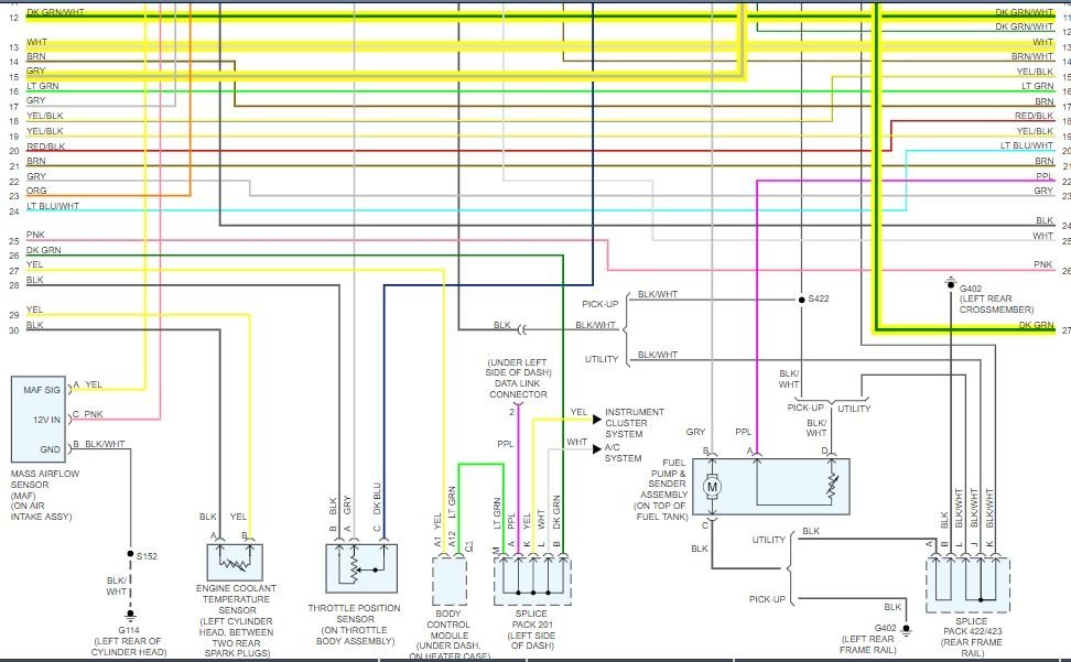
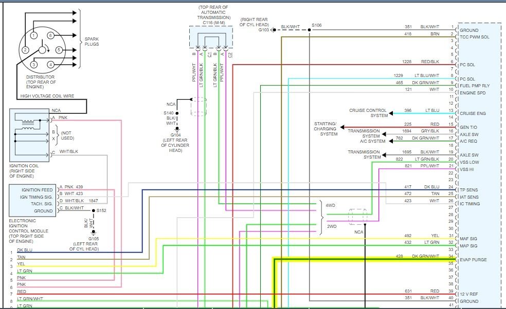
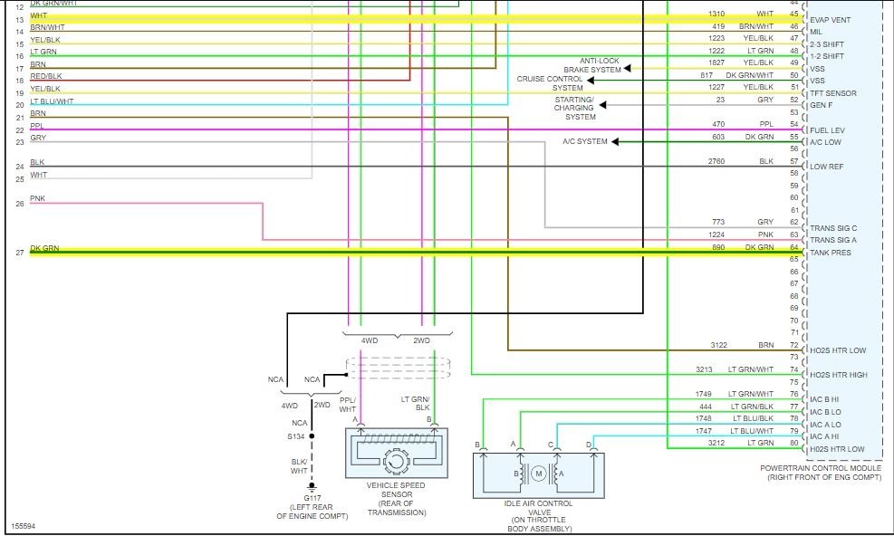
I attached a wiring diagram as well for you. Make sure you have 12 volts to the vent solenoid and purge solenoid with the key on. Also, verify 5 volts to the fuel tank pressure sensor.
https://www.2carpros.com/articles/how-to-check-wiring
Roy
DESCRIPTION
The evaporative emission (EVAP) large leak test applies vacuum to the EVAP system and monitors vacuum decay. The control module monitors the fuel tank pressure (FTP) sensor signal in order to determine the vacuum decay rate. At an appropriate time, the control module turns the EVAP canister purge valve ON, open, and the EVAP vent valve ON, closed. This allows the engine to draw a vacuum on the EVAP system. At a calibrated time, or vacuum level, the control module turns the purge valve OFF, closed, sealing the system, and monitors the FTP sensor input in order to determine EVAP system vacuum. If the system is unable to achieve the calibrated vacuum level, or the vacuum level decreases too rapidly, DTC P0440 will set.
CONDITIONS FOR RUNNING THE DTC
DTCs P0107, P0108, P0112, P0113, P0116, P0117, P0118, P0121, P0122, P0123, P0125, P0443, P0449, P0452, P0453, P1111, P1112, P1114, P1115, P1121, or P1122 are not set.
The ignition voltage is between 10-18 volts.
The barometric pressure (BARO) is more than 75 kPa.
The fuel level is between 15-85 percent.
The engine coolant temperature (ECT) is between 4-30°C (39-86°F).
The intake air temperature (IAT) is between 4-30°C (39-86°F).
The start-up ECT and IAT are within 9°C (16°F) of each other.
The vehicle speed sensor (VSS) is less than 121 km/h (75 mph).
CONDITIONS FOR SETTING THE DTC
The EVAP system is not able to achieve or maintain vacuum during the diagnostic test.
ACTION TAKEN WHEN THE DTC SETS
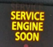
The control module illuminates the malfunction indicator lamp (MIL) on the second consecutive ignition cycle that the diagnostic runs and fails.
The control module records the operating conditions at the time the diagnostic fails. The first time the diagnostic fails, the control module stores this information in the Failure Records. If the diagnostic reports a failure on the second consecutive ignition cycle, the control module records the operating conditions at the time of the failure. The control module writes the operating conditions to the Freeze Frame and updates the Failure Records.
CONDITIONS FOR CLEARING THE MIL/DTC
The control module will turn the malfunction indicator lamp (MIL) OFF during the first consecutive trip in which the diagnostic has been run and passed.
A current DTC, Last Test Failed, clears when the control module turns OFF the MIL.
The history DTC will clear after the control module runs and passes 40 consecutive warm up cycles with no failure.
Use the scan tool in order to clear the DTC.
DIAGNOSTIC AIDS
Use the J 41413 EVAP Pressure/Purge Diagnostic Station in order to pressurize the EVAP system to aid in locating intermittent leaks. Move all EVAP components while testing with the J 41416 Ultrasonic Leak Detector.
A temporary blockage in the EVAP canister purge valve, purge pipe, or EVAP canister could cause an intermittent condition. To repair a blockage in the EVAP system, refer to Evaporative Emission (EVAP) System Cleaning.
Reviewing the Failure Records vehicle mileage since the diagnostic test last failed may help determine how often the condition that caused the DTC to be set occurs. This may assist in diagnosing the condition.
Images (Click to make bigger)
SPONSORED LINKS
Friday, October 16th, 2020 AT 4:34 AM
