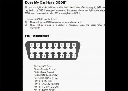
Trace the wire from terminal 2, on the connector, it is shorted to ground, or the terminal at Pin 5 is shorted to power, 2 is the class 2 line and 5 is the class 2 ground.
Conditions for Running the DTCs � � � Voltage supplied to the module is in the normal operating voltage range. � � � The vehicle power mode requires serial data communication to occur. Conditions for Setting the DTCs � � � No valid messages are detected on the class 2 serial data circuit. � � � The voltage level detected on the class 2 serial data circuit is under one of the following conditions: � � � Always high � � � Always low � � � The above conditions are met for approximately 3 seconds. Action Taken When the DTCs Sets � � � The module inhibits the setting of all other class 2 DTCs. � � � The module uses default values for all parameters received on the class 2 serial data circuit. Conditions for Clearing the DTC � � � A current DTC clears when the malfunction is no longer present. � � � A history DTC clears when the module ignition cycle counter reaches the reset threshold, without a repeat of the malfunction. Diagnostic Aids � � � These DTCs cannot be retrieved with a current status. Diagnosis of current DTCs is accomplished via the symptom, Scan Tool Does Not Communicate with a Class 2 Device. Refer to Scan Tool Does Not Communicate with Class 2 Device . � � � An intermittent condition is likely to be caused by a short or an open on the class 2 serial data circuit. Use the Scan Tool Does Not Communicate with a Class 2 Device procedure in order to isolate an intermittent condition. Refer to Scan Tool Does Not Communicate with Class 2 Device . SCAN TOOL DOES NOT POWER UP Circuit Description The data link connector (DLC) is a standardized 16 cavity connector. Connector design and location is dictated by an industry wide standard, and is required to provide the following: � � � Scan tool power battery positive voltage at terminal 16. � � � Scan tool power ground at terminal 4. � � � Common signal ground at terminal 5. The scan tool will power up with the ignition Off. Some modules however, will not communicate unless the ignition is On and the power mode master (PMM) module sends the appropriate power mode message. Test Description The number below refers to the step number on the diagnostic table. 4. If the battery positive voltage and ground circuits of the DLC are functioning properly. The malfunction must be due to the scan tool. Fig. 11: Scan Tool Does Not Power Up Courtesy of GENERAL MOTORS CORP. SCAN TOOL DOES NOT COMMUNICATE WITH CLASS 2 DEVICE Circuit Description Modules connected to the class 2 serial data circuit monitor for serial data communications during normal vehicle operation. Operating information and commands are exchanged among the modules. Connecting a scan tool to the DLC allows communication with the modules for diagnostic purposes. Diagnostic trouble codes (DTCs) may be set due to this symptom and during this diagnostic procedure. Complete the diagnostic procedure in order to ensure all the DTCs are diagnosed and cleared from memory. Diagnostic Aids � � � If a short to B+ is present, a history U1301 or U1305 will set in the modules. Refer to DTC U1300, U1301, or U1305 (Generic Short DTC) . � � � If a short to ground is present, a history U1300 or U1305 will set in the modules. Refer to DTC U1300, U1301, or U1305 (Generic Short DTC) . � � � Disconnecting modules and turning the ignition switch to RUN may cause DTCs in these modules. Check for DTCs in each module upon completion of the required repair. � � � The scan tool cannot directly communicate to the Rear Video/Audio/HVAC or Video Disc Player. Diagnosis is accomplished by checking communications with the Radio. Test Description The numbers below refer to the step numbers on the diagnostic table. 2. A partial malfunction in the class 2 serial data circuit uses a different procedure from a total malfunction of the class 2 serial data circuit. 3. DTCs U1300, U1301, or U1305 may be retrieved with a history status. These DTCs are not the cause of the present condition. 6. A state of health DTC with a history status may be present along with a U1000 having a current status. This indicates the malfunction occurred when the ignition was on. 7. Data link connector terminals 2 and 5 provide the connection to the class 2 serial data circuit and the signal ground circuit respectively. 9. poor connection at the DLC terminal would cause this condition but will not set a DTC. 10. An open in the class 2 serial data circuit between the DLC and the star connector will prevent the scan tool from communicating with any module. This condition will not set a DTC. 11. The class 2 serial data circuit is shorted to voltage or ground. The condition may be due to the wiring or due to a malfunction in one of the modules. When testing the wiring for a short, make sure there is not a module connected to the wire being tested. This test isolates the PCM class 2 serial data circuit. 13. his test isolates the SDM class 2 serial data circuit. 15. This test isolates the EBCM class 2 serial data circuit. 17. This test isolates the IPC class 2 serial data circuit. 19. This test isolates the PK3 class 2 serial data circuit. 21. This test isolates the DIC class 2 serial data circuit. 23. This test isolates the Radio class 2 serial data circuit. 33. If there are no current DTCs that begin with a "U", the communication malfunction has been repaired. 35. The communication malfunction may have prevented diagnosis of the customer complaint.
The modules are numbered to aid in identification of what Class 2 device isn't communication, your is the IPC Instrument panel cluster and the theft deterrent module.

Monday, August 23rd, 2010 AT 1:40 PM


