Hi lmanzo,
Here are the diagnostics for P1400.
DTC P1400 - EGRC SOLENOID
1. Check Power Supply
Turn ignition off. Disconnect EGRC solenoid valve harness connector. Turn ignition on. Using a voltmeter, measure voltage between EGRC solenoid valve harness connector terminal No. 2 (Red/Yellow wire) and ground. If battery voltage does not exist, check for blown fuse No. 17 or fault in Red/Yellow wire. Replace or repair as required. If battery voltage exists, go to next step.
2. Check Output Signal Circuit
Turn ignition off. Disconnect ECM harness connector. Using an ohmmeter, check continuity between EGRC solenoid valve harness connector terminal No. 1 (Blue/Black wire) and ECM harness connector terminal No. 103. If no continuity exists, repair open in Blue/Black wire. If continuity exists, go to next step.
3. Check Components
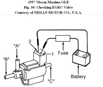
Apply battery voltage and ground to terminals No. 1 and 2. See Fig. 30. With battery voltage applied, air should pass between ports "A" and "B". Air should not pass between ports "A" and "C". With no voltage applied, air should pass between ports "A" and "C". Air should not pass between ports "A" and "B". Replace EGRC valve if airflow is not as specified. If airflow is as specified, disconnect and reconnect harness connectors in circuit and retest system.

Thursday, October 21st, 2010 AT 2:07 PM


