Hi picvijam, Welcome to 2carpros and TY for the donation
Do you have a check engine light and when was the last tune-up and transmission service-
Check the transmission fluid condition and level, also gear shift linkage if okay do below
For a start -Inspect and test the transmission range sensor
TEST D: TRANSMISSION RANGE (TR) SENSOR (1997 SABLE & TAURUS
3.0L-2V)
AX4N Electronic Diagnostics Disconnect TR connector, and inspect it for damaged pins, corrosion and loose wires. Repair as necessary. Reconnect TR connector. Ensure TR sensor is correctly adjusted. See FORD AX4N overhaul article. If sensor requires adjustment, clear trouble codes after adjustment. See CLEARING CODES . Repeat QUICK TEST . If sensor is correctly adjusted, go to next step.
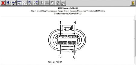
Check Electrical Signal Operation Ensure ignition is off. Disconnect TR sensor harness connector. Turn ignition on. Measure voltage between harness connector terminals No. 2 and 3. See Fig. 5 . If voltage is 4.75-5.25 volts, go to step 5). If voltage is not within specification, go to next step.

Check Continuity Of TR Sensor Harness Circuits Turn ignition off. Disconnect PCM 104-pin connector, and inspect it for damaged pins, corrosion and loose wires. Repair as necessary. Install breakout box, leaving PCM disconnected. Measure and record resistance between breakout box test pin terminal No. 91 and TR harness connector terminal No. 2. Measure and record resistance between breakout box test pin terminal No. 64 and TR harness connector terminal No. 3. See Fig. 5 . If each resistance is less than 5 ohms, go to next step. If any resistance is more than 5 ohms, repair open circuit. Remove breakout box and connect all components. Erase all trouble codes. See CLEARING CODES . Repeat QUICK TEST .
Check TR Circuit For Shorts To Power & Ground Measure resistance between breakout box test pin No. 64 and test pins No. 24, 51, 71, 76, 77, 91, 97 and 103. Measure resistance between breakout box test pin No. 64 and ground. If each measurement is more than 10 k/ohms, go to next step. If any measurement is less than 10 k/ohms, repair short circuit. Remove breakout box and connect all components. Erase all trouble codes. See CLEARING CODES . Repeat QUICK TEST .
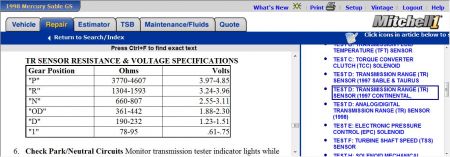
Check TR Sensor Resistance Install TR overlay on transmission tester. Connect tester to TR sensor. Check continuity and resistances in all positions. See TR SENSOR RESISTANCE & VOLTAGE SPECIFICATIONS table. If TR sensor does not operate within specification, replace sensor. Connect all components. Erase all trouble codes. See CLEARING CODES . Repeat QUICK TEST . If sensor operates within specification, replace PCM. Connect all components. Erase all trouble codes. See CLEARING CODES. Repeat QUICK TEST.
TR SENSOR RESISTANCE & VOLTAGE SPECIFICATIONS

Check Park/Neutral Circuits Monitor transmission tester indicator lights while moving gear shift lever through all positions. If indicator light display matches gear shift lever position, go to next step. If indicator light display does not match gear shift lever position, replace TR sensor. Connect all components. Erase all trouble codes. See CLEARING CODES . Repeat QUICK TEST .
Check Reverse/Back-Up Light Circuits Monitor transmission tester indicator light while moving gear shift lever to Reverse position. Verify if back-up lights are illuminated. If indicator light display matches gear shift lever position and back-up lights operate correctly, system is currently operating correctly. If indicator light display does not match gear shift lever position and/or back-up lights are not illuminated, replace TR sensor. Connect all components. Erase all trouble codes. See CLEARING CODES . Repeat QUICK TEST .
SPONSORED LINKS
Monday, October 11th, 2010 AT 6:03 AM


