Test it this way first:
STEERING COLUMN SWITCHES -1995 Mercury Sable GS
Page 1 of 1
IGNITION SWITCH
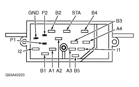
1.Test for continuity between specified terminals with switch in each position. See Fig. 3 . If continuity is not as specified, or is poor in any switch position, replace ignition switch.
Fig. 3: Identifying Ignition Switch Terminals (Sable & Taurus) Courtesy of FORD MOTOR CO.
2.Continuity should exist between terminals B5 and I1 with switch in START and RUN positions only. Continuity should not exist for all other switch positions. 3.Continuity should exist between terminals B5 and A1 with switch in ACC position only. Continuity should not exist for any other switch position. 4.Continuity should exist between terminals A1 and B1 with switch in RUN position only. Continuity should not exist for any other switch position. 5.Continuity should exist between terminals A2 and B2 with switch in RUN position only. Continuity should not exist for any other switch position. 6.Continuity should exist between terminals A3 and B3 with switch in RUN position only. Continuity should not exist for any other switch position. 7.Continuity should exist between terminals A4 and B4 with switch in RUN position only. Continuity should not exist for any other switch position.
IGNITION SWITCH
Removal
Disconnect negative battery cable. Remove steering column shroud. Remove tilt lever (if equipped). Remove instrument panel lower column cover. Unplug ignition switch connector. Set ignition switch to RUN position. Remove ignition switch.
Installation
Set ignition switch to RUN position by turning ignition switch shaft to START position, then releasing shaft. Install ignition switch. Connect ignition switch wiring. Connect negative battery cable. Check operation of ignition switch. To complete installation, reverse removal procedure.

Saturday, October 18th, 2008 AT 8:40 PM


